


Chapter 7
7-25
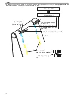
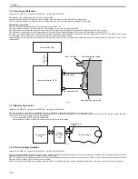
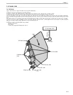
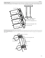
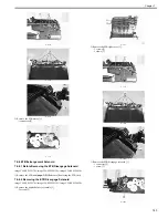
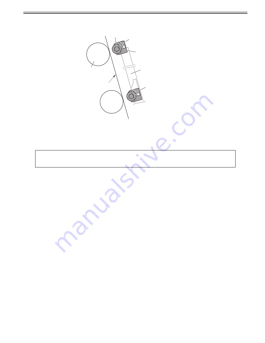
(c) Upward position (All colors' transfer rollers are disengaged)
When the transfer roller disengagement slider is placed at the upward position, the transfer roller holder moves to the highest position along the slope 2, so the
all colors' transfer rollers are disengaged from the ETB.
F-7-31
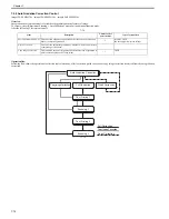
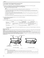
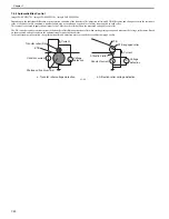
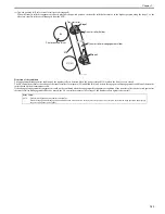
Detection of the condition
The engagement/disengagement condition of the transfer roller is detected when the power is turned ON or when the front cover is closed.
The DC controller measures the voltage of the transfer rollers for magenta (M) and black (Bk), and detects the engagement/disengagement condition of the transfer
rollers based on the measurement result.
If the change of engagement/disengagement could not be confirmed when the engagement/disengagement condition of the transfer rollers was detected again after
the transfer roller disengagement slider was moved, the DC controller measures the voltage of the transfer rollers again (retry control).
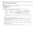
Error Codes:
E078
Transfer disengagement mechanism abnormality
When the engagement/disengagement condition could not be detected correctly after retry control was executed, the machine stops operation and displays
the error code on the control panel.
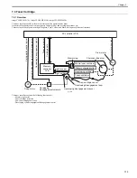
Photosensitive drum
ETB
Transfer roller
Transfer roller holder
Transfer roller disengagement slider
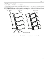
Bk
Y(C,M)
Slope2
Slope2
Summary of Contents for imageCLASS MF8450c
Page 16: ...Chapter 1 Introduction ...
Page 55: ...Chapter 2 Basic Operation ...
Page 61: ...Chapter 3 Main Controller ...
Page 75: ...Chapter 4 Original Exposure System ...
Page 88: ...Chapter 5 Original Feeding System ...
Page 105: ...Chapter 6 Laser Exposure ...
Page 113: ...Chapter 7 Image Formation ...
Page 150: ...Chapter 8 Pickup and Feed System ...
Page 184: ...Chapter 9 Fixing System ...
Page 200: ...Chapter 10 External and Controls ...
Page 230: ...Chapter 11 Maintenance and Inspection ...
Page 233: ...Chapter 12 Measurement and Adjustments ...
Page 237: ...Chapter 13 Correcting Faulty Images ...
Page 260: ...Chapter 14 Error Code ...
Page 272: ...Chapter 15 Special Management Mode ...
Page 280: ...Chapter 16 Service Mode ...
Page 322: ...Chapter 17 Upgrading ...
Page 327: ...Chapter 17 17 4 3 Click Next F 17 4 4 Select a USB connected device and click Next F 17 5 ...
Page 328: ...Chapter 17 17 5 5 Click Start F 17 6 6 Click Yes F 17 7 Download will be started F 17 8 ...
Page 330: ...Chapter 18 Service Tools ...
Page 334: ...Appendix ...
Page 349: ......


