Chapter 10
10-6
10.4 Power Supply
10.4.1 Power Supply
10.4.1.1 Low-voltage Power Unit
0020-2570
imageCLASS MF9170c / imageCLASS MF9150c / imageCLASS MF8450c
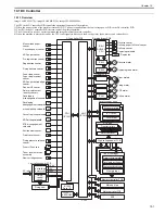
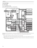
The low-voltage power PCB is to convert AC into DC covering the DC loads.
F-10-3
The low-voltage power PCB is partially activated as soon as plugged in the electrical outlet. When turning ON the power switch (SW4), whole low-voltage power
supply works.
The AC power is then converted into +24V, +5V and +3.3V covering each of machine DC loads. The following are the main loads for each power.
+24V:
Main controller PCB, high-voltage power PCB, Motors, solenoids, fans, reverse unit, and ADF
+5V:
Main controller PCB, driver PCB, laser driver PCB, high-voltage power PCB, memory controller PCB, color displacement/density sensor, and control
panel
+3.3V:
DC controller PCB, main controller PCB, driver PCB, high-voltage power PCB, memory controller PCB, sensor (photo interrupter), environment sensor,
fixing unit, control panel, reverse unit, and ADF
CPU
(IC1001)
Noise filter
Fuse
Power switch
Fuse
Noise filter
Low-voltage power circuit
Remote switch
control circuit
Zero crossing
circuit
24V ON/OFF circuit
24V generation
circuit
5V generation circuit
3.3V generation circuit
Machine power supply
voltage detection circuit
ASIC
(IC1010)
PS100V
3.3V
5V
24VA
PSREM24V
ZEROX
PSOFF
/PSSWOPEN
FSRD
RLD-
DC controller
PCB
Driver PCB
Front cover detection switch
24VA
24VB
24VA
24VB
3.3V 5V
RLD+
Fixing unit
3.3V
Reverse unit
3.3V
24VB
Pickup motor Drum motor
ETB motor Fixing motor
Solenoids
24VB
Photointerrupters
3.3V
High-voltage power PCB
3.3V
24VB
5V
Fan
Scanner motor
24VA
Laser driver PCB
5V
5V
3.3V
Memory controller PCB
Environment sensor
Photointerrupters
3.3V
5V
3.3V
Main controller PCB
Control panel
ADF
Fixing
control
circuit
Low-voltage power PCB
Color displacement/density sensor
SW4
FU3801
FU3901
Protective circuit
Summary of Contents for imageCLASS MF8450c
Page 16: ...Chapter 1 Introduction ...
Page 55: ...Chapter 2 Basic Operation ...
Page 61: ...Chapter 3 Main Controller ...
Page 75: ...Chapter 4 Original Exposure System ...
Page 88: ...Chapter 5 Original Feeding System ...
Page 105: ...Chapter 6 Laser Exposure ...
Page 113: ...Chapter 7 Image Formation ...
Page 150: ...Chapter 8 Pickup and Feed System ...
Page 184: ...Chapter 9 Fixing System ...
Page 200: ...Chapter 10 External and Controls ...
Page 230: ...Chapter 11 Maintenance and Inspection ...
Page 233: ...Chapter 12 Measurement and Adjustments ...
Page 237: ...Chapter 13 Correcting Faulty Images ...
Page 260: ...Chapter 14 Error Code ...
Page 272: ...Chapter 15 Special Management Mode ...
Page 280: ...Chapter 16 Service Mode ...
Page 322: ...Chapter 17 Upgrading ...
Page 327: ...Chapter 17 17 4 3 Click Next F 17 4 4 Select a USB connected device and click Next F 17 5 ...
Page 328: ...Chapter 17 17 5 5 Click Start F 17 6 6 Click Yes F 17 7 Download will be started F 17 8 ...
Page 330: ...Chapter 18 Service Tools ...
Page 334: ...Appendix ...
Page 349: ......

