Chapter 16
16-15
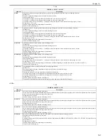
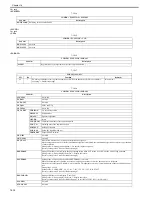
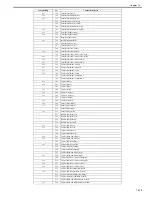
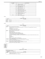
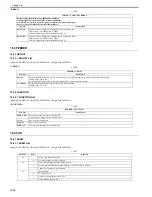
<PRINTER>
T-16-19
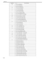
<VIFFNC>
T-16-20
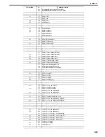
<SPLMAN>
T-16-21
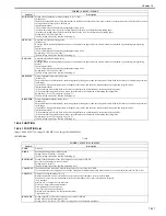
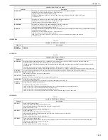
APS-LTLG
Switching of whether or not to display "Automatic (LTR/LGL)" (For future expansion)
Setting value: 0: Do not display the item, 1: Display the item
[Factory setting value/Value after RAM clearing:
0: MF9330C/ MF9340C/ MF9370C/ iR C1021/ iR C1021i/ iR C1022/ iR C1022i/ iR C2110F/ iR C2110N
1: Other models]
DSP-SCWD
Switching of whether or not to enable ScanToMedia (For future expansion)
Setting value: 0: Enable the function, 1: Disable the function
[Factory setting value/Value after RAM clearing: 0]
DSP-MDPR
Switching of whether or not to enable MediaPrint (For future expansion)
Setting value: 0: Enable the function, 1: Disable the function
[Factory setting value/Value after RAM clearing: 0]
DSP-ACS
Switching of whether or not to display [ACS Function Adjustment] when selecting [Additional Func.] > [Adjustment/Cleaning] >
[ACS Function Adjustment].
Setting value: 0: Do not display the item, 1: Display the item
[Factory setting value/Value after RAM clearing:
0: IR C1022i / IR C1021I / iRC 1021i / IRC 1022 / iRC 1021 for North America, Europe, and Australia
1: Other models]
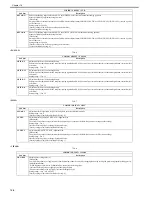
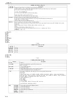
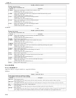
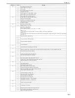
COPIER > FUNCTION > PRINTER
Sub item
Description
SYS-SW
Not used
SYS-NUM
Not used
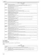
COPIER > FUNCTION > VIFFNC
Sub item
Description
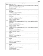
RSTR-DCN
Restoration of the backup information of DC controller NVRAM retained in the controller's NVRAM to the DC controller NVRAM
Perform the following procedure after replacement of the DC controller PCB.
1) Using this item, restore the backup data of the DC controller retained in the NVRAM of the main controller PCB to the NVRAM of the DC
controller PCB.
2) Print the user data list by selecting "Initial setting/registration > Report output > List print > User data list".
3) Execute full correction by selecting "Initial setting/registration > Adjustment > Cleaning > Automatic gradation correction > Full correction".
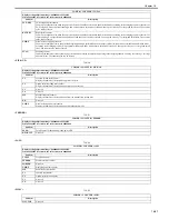
CLR-DCN
Clear of the backup information of DC controller NVRAM retained in the controller's NVRAM to the DC controller NVRAM
SEL-TALC
Setting of TALC paper
ETB cleaning is performed 10 times at initial rotation.
INV-ATVC
Setting to enable ATVC
Ignore ATVC and use a default value for the output value of each bias.
IMP-BNDG
Setting for banding improvement
Perform idling with engagement of the developing assembly and disengagement of ETB.
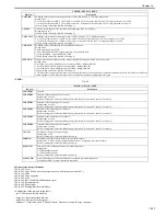
AANY-0
/ AANY-1
Setting of any-any mode 0 / any-any mode 1
Combination of any-any mode 0 / any-any mode 1
AANY-0=0/AANY-1=0: Perform constant-speed cleaning after a job only when the paper size does not match.
AANY-0=1/AANY-1=0: Perform high-speed cleaning after all jobs.
AANY-0=0/AANY-1=1: Perform constant-speed cleaning after all jobs.
AANY-0=1/AANY-1=1: Perform high-speed cleaning after a job only when the paper size does not match.
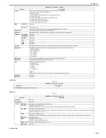
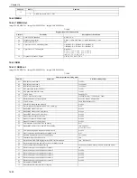
COPIER > FUNCTION > SPLMAN
Sub item
Description
SPL27767
Setting of high-resistance paper
Decrease the final output value of transfer bias by 250V.
(Only when high-humidity OHT/high-humidity gloss film is not specified)
Setting value: 0: OFF, 1: ON
[Factory setting value/Value after RAM clearing: 0]
SPL27267
Setting of 4mil OHT
Decrease the final output value of transfer bias by 500V.
(Only when high-humidity OHT/high-humidity gloss film/high-resistance paper is not specified)
Setting value: 0: OFF, 1: ON
[Factory setting value/Value after RAM clearing: 0]
SPL23866
Setting of calcium carbonate paper
Apply the maximum attraction bias wherever possible regardless of the environment. Since there is no result of detection of attraction paper
resistance, set a transfer bias from the environment.
Setting value: 0: OFF, 1: ON
[Factory setting value/Value after RAM clearing: 0]
COPIER > FUNCTION > PARAM
Sub item
Description
Summary of Contents for imageCLASS MF8450c
Page 16: ...Chapter 1 Introduction ...
Page 55: ...Chapter 2 Basic Operation ...
Page 61: ...Chapter 3 Main Controller ...
Page 75: ...Chapter 4 Original Exposure System ...
Page 88: ...Chapter 5 Original Feeding System ...
Page 105: ...Chapter 6 Laser Exposure ...
Page 113: ...Chapter 7 Image Formation ...
Page 150: ...Chapter 8 Pickup and Feed System ...
Page 184: ...Chapter 9 Fixing System ...
Page 200: ...Chapter 10 External and Controls ...
Page 230: ...Chapter 11 Maintenance and Inspection ...
Page 233: ...Chapter 12 Measurement and Adjustments ...
Page 237: ...Chapter 13 Correcting Faulty Images ...
Page 260: ...Chapter 14 Error Code ...
Page 272: ...Chapter 15 Special Management Mode ...
Page 280: ...Chapter 16 Service Mode ...
Page 322: ...Chapter 17 Upgrading ...
Page 327: ...Chapter 17 17 4 3 Click Next F 17 4 4 Select a USB connected device and click Next F 17 5 ...
Page 328: ...Chapter 17 17 5 5 Click Start F 17 6 6 Click Yes F 17 7 Download will be started F 17 8 ...
Page 330: ...Chapter 18 Service Tools ...
Page 334: ...Appendix ...
Page 349: ......

