Chapter 14
14-5
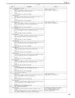
T-14-4
Code
Description
Action
E024
Toner level sensor failure
0000 Description
Failure output from the toner level sensor (Yellow).
Cause
Memory controller PCB assembly fault, DC controller PCB assembly fault, toner
cartridge fault.
- Replace toner cartridge
- Replace memory controller PCB
- Replace DC controller PCB
0001 Description
Failure output from the toner level sensor (Magenta).
Cause
Memory controller PCB assembly fault, DC controller PCB assembly fault, toner
cartridge fault.
0002 Description
Failure output from the toner level sensor (Cyan).
Cause
Memory controller PCB assembly fault, DC controller PCB assembly fault, toner
cartridge fault.
0003 Description
Failure output from the toner level sensor (Black).
Cause
Memory controller PCB assembly fault, DC controller PCB assembly fault, toner
cartridge fault.
E066
Error in environment sensor
0000 Description
Failure in environment sensor.
Cause
Environment sensor fault, DC controller PCB assembly fault.
- Replace environment sensor
- Replace DC controller PCB
E078
Error in primary transfer estrangement unit
0000 Description
Primary transfer estrangement unit does not function properly.
Cause
Terminal assembly fault, transfer roller estrangement solenoid fault, EBT unit fault,
high-voltage power PCB assembly fault.
- Replace ETB estrangement solenoid
- Replace ETB unit
- Terminal assembly fault (check on every contact between the
terminals of each color and the high voltage PCB assembly)
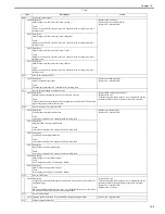
E100
Error in scanner motor, laser unit, BD
0000 Description
Yellow scanner assembly malfunction.
Cause
Laser scanner unit fault, DC controller PCB assembly fault.
- Replace laser scanner unit
- Replace DC controller PCB
0001 Description
Magenta scanner assembly malfunction.
Cause
Laser scanner unit fault, DC controller PCB assembly fault.
0002 Description
Cyan scanner assembly malfunction.
Cause
Laser scanner unit fault, DC controller PCB assembly fault.
0003 Description
Black scanner assembly malfunction.
Cause
Laser scanner unit fault, DC controller PCB assembly fault.
0004 Description
Failure output of a magenta BD signal
Cause
laser scanner unit fault, DC controller PCB fault.
0005 Description
Failure output of a magenta BD signal
Cause
laser scanner unit fault, DC controller PCB fault.
E194
Error in CPR sensor
0000 Description
Cannot detect color displacement detection pattern, detected results fall outside the
acceptable range.
Cause
Dirty color displacement detection sensor, color displacement detection sensor fault,
DC controller PCB assembly fault, toner cartridge fault.
- Replace ETB unit
- Terminal assembly fault (check on every contact between the
terminals of each color and the high voltage PCB assembly)
- Replace DC controller PCB
- Replace toner cartridge
E196
Error in DCON ROM
0001 Updating the ROM on the DC controller PCB assembly has been failed.
- Replace DC controller PCB
E197
Engine communication error
Summary of Contents for imageCLASS MF8450c
Page 16: ...Chapter 1 Introduction ...
Page 55: ...Chapter 2 Basic Operation ...
Page 61: ...Chapter 3 Main Controller ...
Page 75: ...Chapter 4 Original Exposure System ...
Page 88: ...Chapter 5 Original Feeding System ...
Page 105: ...Chapter 6 Laser Exposure ...
Page 113: ...Chapter 7 Image Formation ...
Page 150: ...Chapter 8 Pickup and Feed System ...
Page 184: ...Chapter 9 Fixing System ...
Page 200: ...Chapter 10 External and Controls ...
Page 230: ...Chapter 11 Maintenance and Inspection ...
Page 233: ...Chapter 12 Measurement and Adjustments ...
Page 237: ...Chapter 13 Correcting Faulty Images ...
Page 260: ...Chapter 14 Error Code ...
Page 272: ...Chapter 15 Special Management Mode ...
Page 280: ...Chapter 16 Service Mode ...
Page 322: ...Chapter 17 Upgrading ...
Page 327: ...Chapter 17 17 4 3 Click Next F 17 4 4 Select a USB connected device and click Next F 17 5 ...
Page 328: ...Chapter 17 17 5 5 Click Start F 17 6 6 Click Yes F 17 7 Download will be started F 17 8 ...
Page 330: ...Chapter 18 Service Tools ...
Page 334: ...Appendix ...
Page 349: ......

