Chapter 16
16-34
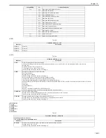
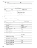
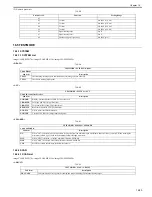
<RKEY>
(1) Numeric parameter
T-16-54
<PBX DIAL TONE>
(1) Bit switch
T-16-55
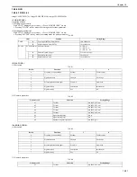
(2) Numeric parameter
T-16-56
<PBX BUSY TONE>
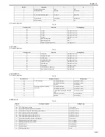
(1) Bit switch
T-16-57
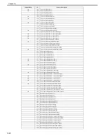
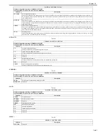
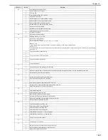
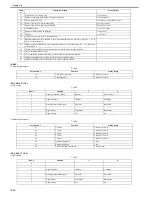
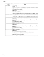
17
Upper limit for F/T calling time
0 to 9999 (sec)
19
Number of trail edge margin (lines) at image's trail edge
0 to 9999 (lines)
20
Time to capture F/T line
0 to 9999 (sec) Special SW17 bit 4
24
Delivery time for V34 control cannel flag
0 to 100 (x 10 ms)
25
Delivery time for V34 primary channel flag
20 to 500 (x 10 ms)
26
V34 fallback speed
1 to 4 (x 2.4 kbps)
27
Number of PPR to start V34 fallback
1 to 9 (times)
30
T2 timer
6 to 30 (sec)
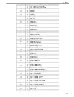
40
Setting T2 timer value for V34 communication
41
Synchronization interval for RETRY to use for synchronization of V8 procedure signal 'PC -> CC' at
the time of receiving FAX
44
Number of times of RETRY to use for synchronization of V8 procedure signal 'PC -> CC' at the time
of receiving FAX
45
Wait time when the DT detection function that is executed before calling is disabled
46
Time to identify DialTone signal
47
Time of not being disconnected in the case that DialTone signal is disconnected
65
Number of maximum lines of A4 paper at the time of sending cut paper
66
Number of maximum lines of B4 paper at the time of sending cut paper
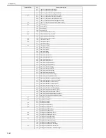
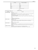
Parameter No.
Function
Setting Range
01
Flash connection time
0 to 9999 (x 10 ms)
02
Grounding time
0 to 9999 (x 10 ms)
Bit No.
Function
1
0
0
Frequency sensing method
Modem
Tonal counter
1
2
Signal frequency
Changes
No change
3
4
Screening intermittent signal
From ON
From both
5
6
Signal format
Continuous
Intermittent
7
Signal sensing
Yes
No
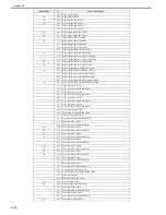
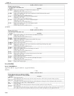
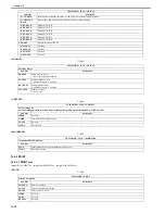
Parameter No.
Function
Setting Range
01
T0 timer
0 to 9999 (x 10 ms)
02
T1 timer
0 to 9999 (x 10 ms)
03
T2 timer
0 to 9999 (x 10 ms)
04
T3 timer
0 to 9999 (x 10 ms)
05
T4 timer
0 to 9999 (x 10 ms)
06
Signal sensing table
0 to 16
07
Signal sensing level
0 to 9
08
Number of signal frequencies
0 to 9999 (pce)
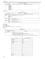
Bit No.
Function
1
0
0
1
2
Signal frequency
Changes
No change
3
4
Screening intermittent signal
From ON
From both
5
6
Signal format
Continuous
Intermittent
7
Signal sensing
Yes
No
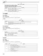
Numb
er
Setting Description
Setting Range
Summary of Contents for imageCLASS MF8450c
Page 16: ...Chapter 1 Introduction ...
Page 55: ...Chapter 2 Basic Operation ...
Page 61: ...Chapter 3 Main Controller ...
Page 75: ...Chapter 4 Original Exposure System ...
Page 88: ...Chapter 5 Original Feeding System ...
Page 105: ...Chapter 6 Laser Exposure ...
Page 113: ...Chapter 7 Image Formation ...
Page 150: ...Chapter 8 Pickup and Feed System ...
Page 184: ...Chapter 9 Fixing System ...
Page 200: ...Chapter 10 External and Controls ...
Page 230: ...Chapter 11 Maintenance and Inspection ...
Page 233: ...Chapter 12 Measurement and Adjustments ...
Page 237: ...Chapter 13 Correcting Faulty Images ...
Page 260: ...Chapter 14 Error Code ...
Page 272: ...Chapter 15 Special Management Mode ...
Page 280: ...Chapter 16 Service Mode ...
Page 322: ...Chapter 17 Upgrading ...
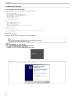
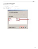
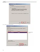
Page 327: ...Chapter 17 17 4 3 Click Next F 17 4 4 Select a USB connected device and click Next F 17 5 ...
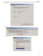
Page 328: ...Chapter 17 17 5 5 Click Start F 17 6 6 Click Yes F 17 7 Download will be started F 17 8 ...
Page 330: ...Chapter 18 Service Tools ...
Page 334: ...Appendix ...
Page 349: ......

