


ADIN0
ADIN31
Self-test and
calibration
AD
REFLO
AD
REFHI
V
in
R2
R1
S4
S1 S2
S3
S5
ADC Core
ADDRx.16,9:0
ADCALR.9:0
CALR
MUX
R1 ~ 5K
R2 ~ 7K
ADC Special Modes
713
SPNU503C – March 2018
Copyright © 2018, Texas Instruments Incorporated
Analog To Digital Converter (ADC) Module
19.8.2 ADC Self-Test Mode
The ADC module supports a self-test mode which can be used to detect an open or a short on the ADC
input channels. Self-test mode is enabled by setting the SELF_TEST bit (ADCALCR.24). Any conversion
type (continuous or single conversion, freeze enabled or non-freeze enabled, interrupts enabled or
disabled) can be performed in this mode.
In normal mode, setting the self-test mode while a conversion sequence is in process can corrupt the
current channel conversion results. However, the next channel in the sequence is converted correctly
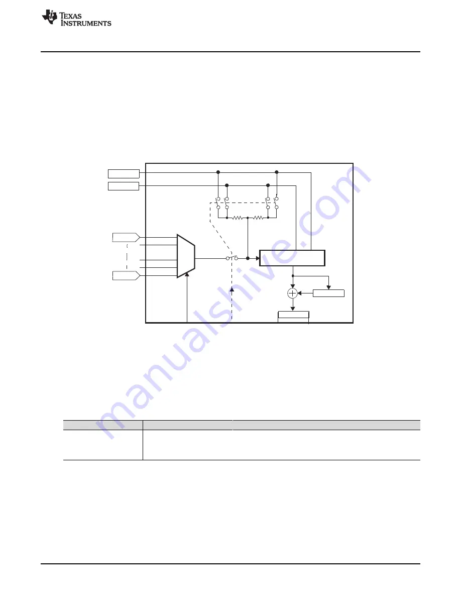
during the additional self-test cycle. The logic associated with both self-test and calibration is shown in
.
Figure 19-13. Self-Test and Calibration Logic
In self-test mode, a test voltage defined by the HILO bit (ADCALCR.8) is provided to the ADC core input
through a resistor (see
). To change the test source, this bit can be toggled before any single
conversion mode request. Changing this bit while a conversion is in progress
can
corrupt the results if the
source switches during the acquisition period.
Please note that the switch S5 shown in
is only for the purpose of explaining the self-test
sequence. There is no physical switch.
(1)
Switches refer to
.
Table 19-2. Self-Test Reference Voltages
(1)
SELF_TEST
HILO
S1
S2
S3
S4
S5
Reference Voltage
1
0
0
1
1
0
1
AD
REFLO
via R1 || R2 connected to V
in
1
1
1
0
0
1
1
AD
REFHI
via R1 || R2 connected to V
in
0
X
0
0
0
0
1
V
in


