background image

YH4

GRAND

VITARA

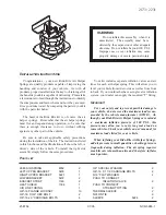
1. Gaging plastic
2. Scale

6A1-36

ENGINE MECHANICAL (G16 ENGINE)

Camshaft Journal Wear

Check camshaft journals and camshaft housings for pitting,
scratches, wear or damage.
If any malcondition is found, replace camshaft or cylinder head with
housing. Never replace cylinder head without replacing housing.

Check clearance by using gaging plastic.
The procedure is as follows.
1) Clean housing and camshaft journals.
2) Install camshaft to cylinder head.
3) Place a piece of gaging plastic the full width of journal of cam-

shaft (parallel to camshaft).

4) Install camshaft housing, referring to page 6A1-38.
5) Tighten camshaft housing bolts in such order as indicated in fig-

ure a little at a time till they are tightened to specified torque.

Tightening Torque
(a): 11 N

.

m (1.1kg-m, 8.0 lb-ft)

NOTE:
Do not rotate camshaft while gaging plastic is installed.

6) Remove housing and using scale on gaging plastic envelope,

measure gaging plastic width at its widest point.

Standard

Limit

Journal
clearance

0.040 – 0.082 mm

(0.0016 – 0.0032 in.)

0.12 mm

(0.0047 in.)

Содержание 2000 Grand Vitara SQ416

Страница 1: ...compo nents or wiring Modifications can adverse ly affect air bag system performance and lead to injury If the vehicle will be exposed to tempera tures over 93 C 200 F for example during a paint baki...

Страница 2: ...e contents are classified into sections each of which is given a section number as indicated in the Table of Contents on next page And on the first page of each individual section is an index of that...

Страница 3: ...ntials Front and Rear of SQ series SQ416 SQ420 SQ625 Wiring Diagram Manual 99512 65D10 015 Applicable model mentioned in FOREWORD of this manual SQ416 SQ420 SQ625 Service Manual 99500 65D00 xxx Vehicl...

Страница 4: ...Instrumentation Driver Information Windows Mirrors Security and Lock Immobilizer Control System BODY SERVICE RESTRAINT SYSTEM Seat Belt Air Bag System GENERAL INFORMATION General Information Maintena...

Страница 5: ...r of these two conditions may result in severe injury Technical service work must be started at least 90 seconds after the ignition switch is turned to the LOCK position and the negative cable is disc...

Страница 6: ...on 6 60 DTC P0136 HO2S 2 Circuit Malfunction 6 62 DTC P0141 HO2S 2 Heater Circuit Malfunction 6 64 DTC P0171 Fuel System too Lean or DTC P0172 Fuel System too Rich 6 66 DTC P0300 Random Misfire Detect...

Страница 7: ...es should be disconnected before any major work is performed on the engine Failure to disconnect cables may result in damage to wire harness or other electrical parts Throughout this manual the four c...

Страница 8: ...ry cover fitting to be disconnected with a shop cloth Put that cloth in an approved con tainer when disconnection is completed Never run engine with fuel pump relay disconnected when engine and exhaus...

Страница 9: ...its connector 3 Remove fuel filler cap to release fuel vapor pressure in fuel tank and then reinstall it 4 Start engine and run it till it stops for lack of fuel Repeat cranking engine 2 3 times for...

Страница 10: ...IC SYSTEM VEHICLE WITHOUT MONITOR CONNECTOR ECM PCM in this vehicle has the following functions When the ignition switch is turned ON with the engine at a stop MIL turns ON to check the bulb of the ma...

Страница 11: ...or stopped where air fuel mixture was lean or rich when a malfunc tion was detected by checking the freeze frame data Also ECM PCM has a function to store each freeze frame data for three dif ferent m...

Страница 12: ...P0400 detection Data at P0400 detection Data at P0400 detection Data at P0400 detection Data at P0171 detection Data at P0171 detection Data at P0171 detection Data at P0300 detection Data at P0300 de...

Страница 13: ...ine and Emission Control system is free from any trouble after the engine start while engine is running malfunction indicator lamp 1 turns OFF When ECM detects a trouble which has occurred in the abov...

Страница 14: ...DLC is in compliance with SAEJ1962 in its installation position the shape of connector and pin assignment K line of ISO 9141 is used for SUZUKI scan tool Tech 1 to commu nicate with ECM and ABS contr...

Страница 15: ...ed to the flow table of the DTC which has de tected earliest in the order and follow the instruction in that table If no instructions are given troubleshoot diagnostic trouble codes according to the f...

Страница 16: ...ble Symptom Confirmation in this section Is trouble symptom identified Go to Step 6 Go to Step 7 6 Rechecking and Record of DTC Freeze Frame Data 1 Recheck for DTC and freeze frame data referring to D...

Страница 17: ...ONFIRMATION Based on information obtained in Step 1 Customer complaint analysis and Step 2 DTC freeze frame data check confirm trouble symptoms Also reconfirm DTC according to DTC Confirmation Procedu...

Страница 18: ...on Weather Temperature Frequency Road VFair VCloudy VRain VSnow VAlways VOther ______________ _F _C VHot VWarm VCool VCold VAlways VAlways VSometimes times day month VOnly once VUnder certain conditio...

Страница 19: ...connecting it to ECM PCM in another car If communication is possible in this case scan tool is in good condition Then check data link con nector and serial data line circuit in the car with which comm...

Страница 20: ...data stored in ECM PCM memory are also cleared in following cases Be careful not to clear them before keeping their record D When power to ECM PCM is cut off by disconnecting battery cable removing fu...

Страница 21: ...120 No 21 22 TP SENSOR D Each control except 4 A T is performed on the basis of 124 5_ throttle valve opening D 4 A T control is performed on the basis of 0_ throttle valve opening P0500 No 24 VEHICLE...

Страница 22: ...Max output voltage of HO2S lower than specification g cycles applicable P0133 HO2S circuit slow response Sensor 1 Response time of HO2S 1 output voltage between rich and lean is longer than specificat...

Страница 23: ...on 2 driving cycles Not applicable P0443 Purge control valve circuit malfunction Purge control valve circuit is open or shorted to ground 2 driving cycles Not applicable P0460 Fuel level sensor circui...

Страница 24: ...Refer to Section 7B P0751 Shift Solenoid A 1 Performance or Stuck off Refer to Section 7B P0753 No 61 No 62 Shift Solenoid Valve A 1 P0756 Shift Solenoid B 2 Performance or Stuck off P0758 No 63 No 64...

Страница 25: ...lant Temp J20 70 100_C 158 212_F INTAKE AIR TEMP At specified idle speed after warming up Environmental 35_C temp 5_C DESIRE IDLE Desired Idle Speed At idling with no load after warming up 750 rpm CLO...

Страница 26: ...EGR VALVE At specified idle speed after warming up 0 A C SWITCH if i d When A C not operating OFF if equipped When A C operating ON PSP SWITCH if equipped Engine running at idle speed and steering whe...

Страница 27: ...d at P R N D 2 or L range Vehicle stops OFF TCC SOL CON Torque Converter Clutch Solenoid Command Signal MON Torque Converter Clutch Solenoid Monitor Ignition switch ON Selector lever is shifted at P R...

Страница 28: ...R FLOW RATE g s lb min It represents total mass of air entering intake manifold which is measured by mass air flow sensor CALC LOAD CALCULATED LOAD VALUE Engine load displayed as a percentage of maxim...

Страница 29: ...e fuel pump relay switch FUEL CUT ON OFF ON Fuel being cut output signal to injector is stopped OFF Fuel not being cut EGR VALVE This parameter indicates opening rate of EGR valve which controls the a...

Страница 30: ...A MON OFF Electricity not being passed SHIFT SOL 2 CON MON SHIFT SOLENOID 2 B COMMAND MONITOR ON OFF CON ON ON command being output to shift sole noid 2 B CON OFF ON command not being output MON ON El...

Страница 31: ...ion bend Connectors of electric wire harness disconnection friction Fuses burning Parts installation bolt looseness Parts deformation Other parts that can be checked visually Also add following items...

Страница 32: ...system 7 Is immobilizer control system equipped Go to Step 8 Go to Step 9 8 Check immobilizer system malfunction as follows 1 Check immobilizer indicator lamp or MIL malfunction indicator lamp for fl...

Страница 33: ...hanical Section Cylinder head inspection in Engine Mechanical Section Piston ring inspection in Engine Mechanical Section Cylinders pistons and piston rings inspection in Engine Mechanical Section PCV...

Страница 34: ...System Section ECT sensor TP sensor or MAF sensor in Engine and Emission Control System Section Inspection of ECM PCM and its circuit in this Section Previously outlined PCV system inspection in Engin...

Страница 35: ...n Control System Section Inspection of ECM PCM and its circuit in this Section Excessive detonation The engine makes sharp metallic knocks that change with throttle opening Sounds like pop corn poppin...

Страница 36: ...ector Faulty ECM PCM Low compression Others Poor valve seating Dragging brakes Slipping clutch Thermostat out of order Improper tire pressure Spark plugs in Ignition System Section Diag Flow Table B 3...

Страница 37: ...nder noise Worn piston ring and cylinder bore Connecting rod noise Worn crankpin bearing Worn crankpin Loose connecting rod nuts Low oil pressure Crankshaft noise Low oil pressure Worn crankshaft jour...

Страница 38: ...nd resistance CAUTION PCM ECM cannot be checked by itself It is strictly prohib ited to connect voltmeter or ohmmeter to PCM ECM with couplers disconnected from it Voltage Check 1 Remove PCM ECM cover...

Страница 39: ...r switch 0 1 5 V Ignition switch ON rear defogger switch OFF and lighting switch OFF 15 gg if equipped 10 14 V Ignition switch ON rear defogger switch or lighting switch ON 16 Heater blower switch 10...

Страница 40: ...OFF Ignition switch ON 34 Stop lamp switch 10 14 V Brake pedal depressed switch ON Ignition switch ON 35 1 Intake air temp sensor 2 2 3 0 V Ignition switch ON Sensor ambient temp 20_C 68_F 2 Engine co...

Страница 41: ...solenoid A 10 14 V Ignition switch ON 3 7 8 TCC solenoid 0 1 V Ignition switch ON 9 10 A T input speed sensor About 2 5 V Ignition switch ON 11 A T input speed sensor About 2 5 V Ignition switch ON 12...

Страница 42: ...engine warmed up 5 6 7 4WD air pump assembly 10 14 V Ignition switch ON Transfer lever 4H or 4L range 7 4WD air um assembly if equipped 0 1 V Ignition switch ON Transfer lever 2H range 8 Fuel injecto...

Страница 43: ...tire turned slowly with rear left tire locked 26 Camshaft position sensor Deflects between 0 1 V and 4 6 V Ignition switch ON crankshaft turned slowly 27 Pressure switch in 4WD air 10 14 V Ignition sw...

Страница 44: ...1 3 6 and Body ground Ground Continuity C51 3 17 and Body ground Ground Continuity C51 1 1 and Body ground Shift solenoid B A T C51 1 2 and Body ground Shift solenoid A A T 11 15 C51 1 8 and Body grou...

Страница 45: ...Turn ignition switch ON Do other indicator warning lights in combination meter comes ON Go to Step 2 IG fuse blown main fuse blown Ignition switch malfunction B W circuit between IG fuse and combinat...

Страница 46: ...diagnostic trouble code Go to Step 2 Go to Diagnosis in Section 8G 2 Diag Switch Circuit Check Is diag switch terminal connected to ground via service wire System is in good condition Y circuit short...

Страница 47: ...use 3 Main relay TABLE A 5 ECM PCM POWER AND GROUND CIRCUIT CHECK MIL DOESN T LIGHT AT IGNITION SWITCH ON AND ENGINE DOESN T START THOUGH IT IS CRANKED UP WIRING DIAGRAM CIRCUIT DESCRIPTION When the i...

Страница 48: ...OFF ignition switch disconnect connectors from ECM PCM and install main relay 2 Check for proper connection to ECM PCM at terminals C51 3 20 E61 9 C51 3 15 and C51 3 4 3 If OK then measure voltage be...

Страница 49: ...mA MAF sensor output current continues for 100 msec D MAF sensor circuit open or short D MAF sensor D ECM PCM DTC CONFIRMATION PROCEDURE NOTE Check to make sure that the following conditions are satis...

Страница 50: ...p 3 3 MAF sensor power supply Check 1 With ignition switch OFF disconnect MAF sensor coupler 2 With ignition switch ON check voltage between C32 3 of MAF sensor coupler and ground Is voltage 10 14 V G...

Страница 51: ...intake air temperature or low temperature Low voltage Low resistance or High voltage High resistance D IAT sensor circuit short D IAT sensor D ECM PCM DTC CONFIRMATION PROCEDURE 1 Connect scan tool t...

Страница 52: ...gnition switch ON is voltage applied to LBl wire terminal about 4 6 V Go to Step 4 LBl wire open or shorted to power or poor C51 3 1 connection If wire and connection are OK substitute a known good EC...

Страница 53: ...etected for 5 sec continuously Engine running High engine coolant temperature or Low temperature Low voltage Low resistance or High voltage High resistance ECT sensor circuit short ECT sensor ECM PCM...

Страница 54: ...ition switch ON is voltage applied to Or B wire terminal about 4 6 V Go to Step 4 Or B wire open or shorted to power or poor C51 3 2 connection If wire and connection are OK substitute a known good EC...

Страница 55: ...AREA Following conditions are detected for 5 sec continuously Engine running Signal voltage low or high TP sensor circuit open or short TP sensor ECM PCM DTC CONFIRMATION PROCEDURE 1 Connect scan too...

Страница 56: ...onnector from TP sensor with ignition switch OFF 2 Check for proper connection to TP sensor at each terminals C30 3 and C30 2 3 If OK then with ignition switch ON check voltage between C30 3 and C30 1...

Страница 57: ...M D High resistance in circuit DTC CONFIRMATION PROCEDURE WARNING D When performing a road test select a place where there is no traffic or possibility of a traffic accident and be very careful during...

Страница 58: ...TC P0122 and P0123 Go to applicable DTC Diag Flow Table Go to Step 3 3 Check TP Sensor and its Circuit When using SUZUKI scan tool 1 Turn ignition switch OFF and connect SUZUKI scan tool to DLC 2 Turn...

Страница 59: ...RMATION PROCEDURE P0130 LOW VOLTAGE 4 5 V or more HO2S circuit voltage is detected when 5 V power is connected to HO2S circuit in ECM PCM or Max output voltage of HO2S is 0 6 V or lower on av erage an...

Страница 60: ...barometric pressure 2400 m 8000 ft or less 560 mmHg 75 kPa or more 1 Connect scan tool to DLC with ignition switch OFF 2 Turn ON ignition switch and clear DTC pending DTC and freeze frame data by usin...

Страница 61: ...V indicated Go to Step 4 Go to Step 3 3 HO2S 1 Check 1 With ignition switch OFF disconnect HO2S 1 connector 2 Check for proper connection to HO2S 1 at each terminal 3 If OK connect voltmeter 1 and 2...

Страница 62: ...ayed on scan tool of HO2S 1 output voltage is longer than specification or response rates of Hi Lo and Lo Hi TRANS TIME displayed as R L threshold V or L R threshold V on scan tool are longer than spe...

Страница 63: ...c 3 Repeat racing engine Repeat depressing accelerator pedal 5 to 6 times continuously to enrich A F mixture and take foot off from pedal to enlean and check HO2S output voltage displayed on scan tool...

Страница 64: ...2 driving cycles detection logic D HO2S 1 heater circuit D HO2S 1 heater D ECM PCM DTC CONFIRMATION PROCEDURE NOTE Check to make sure that the following conditions are satisfied when using this DTC C...

Страница 65: ...r 2 Check voltage between C51 2 4 terminal of ECM PCM coupler and body ground with ignition switch ON Is it 10 14 V Go to Step 4 B W or Gr wire open poor HO2S coupler connection Gr wire shorted to gro...

Страница 66: ...V or more HO2S circuit voltage is detected when 5 V power is connected to HO2S circuit in ECM PCM While running with A F feed back average output voltage during specified time is too high or too low o...

Страница 67: ...monitor ing test has completed by using scan tool If not in both of above checks i e no pending DTC and oxygen sen sor monitoring test not completed check vehicle conditions environmental and repeat...

Страница 68: ...and a tester on a level road NOTE Check to make sure that the following conditions are satisfied when using this DTC CONFIRMATION PRO CEDURE D Intake air temp 8_C 18_F or higher D Engine coolant temp...

Страница 69: ...between E61 3 terminal of ECM PCM connector and body ground with ignition switch ON Is it 10 14 V Go to Step 4 B W or P G circuit open shorted to ground If wire and connec tions are OK substi tute a...

Страница 70: ...ION PROCEDURE WARNING D When performing a road test select a place where there is no traffic or possibility of a traffic accident and be very careful during testing to avoid occurrence of an accident...

Страница 71: ...fuel injectors referring to FUEL INJECTOR INSPECTION in ENGINE AND EMISSION CONTROL SYSTEM section Is check result satisfactory Go to Step 6 Faulty injector s 6 Check fuel level sensor referring to DT...

Страница 72: ...compression D Abnormal air drawn in D EGR system D Fuel level sensor D Valve clearance valve lash adjuster D Misfire which causes catalyst to overheat during 200 engine revolutions is detected at 1 c...

Страница 73: ...e 5 Fuel Injector Inspection 1 Check fuel injector s referring to ENGINE AND EMISSION CONTROL SYSTEM section Is check result satisfactory Go to Step 6 Replace 6 Ignition Timing Inspection 1 Check igni...

Страница 74: ...1 Was ENGINE DIAG FLOW TABLE performed Go to Step 2 Go to ENGINE DIAG FLOW TABLE 2 1 With engine running check voltage from C51 3 3 terminal of ECM connector to body ground 2 Is voltage about 0 90 3 9...

Страница 75: ...ENGINE DIAGNOSIS G16 J20 ENGINES 6 71 Fig 1 for Step 3...

Страница 76: ...0 ms Div 2 V Div Waveforms at specified idle speed 10 ms Div 1 CKP sensor 2 Crankshaft timing belt pulley 3 Sensor plate on crankshaft DTC P0335 CRANKSHAFT POSITION SENSOR CIRCUIT MALFUNCTION WIRING D...

Страница 77: ...eck to make sure that the following conditions are satisfied when using this DTC CONFIRMATION PRO CEDURE D Intake air temp 8_C 18_F or higher D Engine coolant temp 8 110_C 18 230_F D Altitude barometr...

Страница 78: ...ry Go to Step 4 Go to Step 3 3 CKP Sensor Resistance Check 1 With ignition switch OFF disconnect CKP sensor coupler 2 Check resistance between terminals of CKP sensor coupler for G16 engine between 2...

Страница 79: ...TC P0340 DTC No 42 CAMSHAFT POSITION SENSOR CIRCUIT MALFUNCTION WIRING DIAGRAM Reference Connect oscilloscope between terminals C51 2 26 and C51 3 26 ground of ECM PCM connector connected to ECM PCM a...

Страница 80: ...or higher D Engine coolant temp 8 110_C 18 230_F D Altitude barometric pressure 2400 m 8000 ft or less 560 mmHg 75 kPa or more 1 Connect scan tool to DLC with ignition switch OFF 2 Turn ON ignition s...

Страница 81: ...nector disconnected Is voltage 4 5 V Go to Step 5 Y Bl wire open short or poor connection If wire and connec tion are OK substi tute a known good ECM PCM and recheck 7 Check CMP Sensor for Operation G...

Страница 82: ...terial attached Is it in good condition J20 Engine Check Signal Rotor 1 Remove rotor cover from CMP sensor 2 Check signal rotor for the following Damage No foreign material attached Is it in good cond...

Страница 83: ...G16 J20 ENGINES 6 79 1 EGR valve 2 Intake manifold 3 Exhaust gas 4 Sensed information 5 Main fuse 6 Main relay 7 MAP sensor 8 Fuse box ECM PCM DTC P0400 EXHAUST GAS RECIRCULATION FLOW MALFUNCTION SYST...

Страница 84: ...ck to make sure that the following conditions are satisfied when using this DTC CONFIRMATION PRO CEDURE D Intake air temp 8_C 18_F or higher D Engine coolant temp 8 110_C 18 230_F D Altitude barometri...

Страница 85: ...r Connec tion in Section 0A Repair or replace 6 EGR Valve Power Supply Circuit Check 1 With ignition switch OFF disconnect EGR valve coupler 2 With ignition switch ON check voltage between C04 2 and g...

Страница 86: ...EGR valve stepping motor or its circuit ECM PCM DTC CONFIRMATION PROCEDURE NOTE Check to make sure that the following conditions are satisfied when using this DTC CONFIRMATION PRO CEDURE D Intake air...

Страница 87: ...o Step 3 EGR valve malfunction 3 Wire Harness Check 1 Connect connector to EGR valve 2 Remove ECM PCM cover and disconnect connector from ECM PCM 3 Check for proper connection to ECM PCM at system rel...

Страница 88: ...voltage of HO2S 2 is maintained at specified level As TWC becomes deteriorated even when the above control is going on the ex haust gas which has passed TWC then passes HO2S 2 at the exhaust oxygen c...

Страница 89: ...50 56 mph 4 Keep above vehicle speed for 5 min or more Throttle valve opening is kept constant in this step 5 Stop vehicle and check if DTC and pending DTC exists by using scan tool If not check if c...

Страница 90: ...rrence of an accident D Road test should be carried out with 2 persons a driver and a tester on a level road NOTE Check to make sure that the following conditions are satisfied when using this DTC CON...

Страница 91: ...stem Check Is check result satisfactory Intermittent trouble or faulty ECM PCM Check for intermittent referring to Intermit tent and Poor Connec tion in Section 0A Go to Step 3 3 Check EVAP canister p...

Страница 92: ...is set to 4H or 4L position front and rear wheels turn at high speed and a very dangerous situ ation may occur 7 Also check that vacuum is felt when engine speed is increased to higher than about 1 5...

Страница 93: ...lity of a traffic accident and be very careful during testing to avoid occurrence of an accident D Road test should be carried out with 2 persons a driver and a tester on a level road NOTE Check to ma...

Страница 94: ...open short 4 VSS Signal Harness Check 1 With ignition switch ON leaving engine OFF check voltage between C20 1 and C20 2 terminal of VSS coupler Is voltage 4 V or more Go to Step 5 Go to Step 6 5 VSS...

Страница 95: ...idle speed for longer than 20 sec continuously or D Engine idle speed is 200 r min or more higher than target idle speed for longer than 20 sec continuously 2 driving cycles detection logic D IAC valv...

Страница 96: ...alve Circuit Check 1 With ignition switch OFF disconnect ECM PCM couplers 2 Check for proper connection to IAC valve at C51 2 3 C51 2 12 C51 2 11 and C51 2 10 terminals 3 If OK check resistance betwee...

Страница 97: ...REA DTC DETECTING CONDITION TROUBLE AREA Data write error or check sum error ECM PCM DTC CONFIRMATION PROCEDURE 1 Connect scan tool to DLC with ignition switch OFF 2 Turn ON ignition switch and clear...

Страница 98: ...hen performing a road test select a place where there is no traffic or possibility of a traffic accident and be very careful during testing to avoid occurrence of an accident D Road test should be car...

Страница 99: ...g 4 6 V or lower Is check result as specified Intermittent trouble or faulty ECM PCM Check for intermit tent referring to Intermittent and Poor Connection in Section 0A Go to Step 3 3 MAP Sensor Check...

Страница 100: ...lity of a traffic accident and be very careful during testing to avoid occurrence of an accident Road test should be carried out with 2 persons a driver and a tester on a level road 1 Connect scan too...

Страница 101: ...E 1 Connect scan tool to DLC with ignition switch OFF 2 Turn ON ignition switch and clear DTC by using scan tool then start engine and run it for 3 min or more 3 Check DTC and pending DTC by using sca...

Страница 102: ...E 1 Connect scan tool to DLC with ignition switch OFF 2 Turn ON ignition switch and clear DTC pending DTC and freeze frame data by using scan tool and run engine at idle speed for 1 min 3 Check DTC an...

Страница 103: ...circuit is in good condition Go to Step 2 2 Fuel Pump Circuit Check 1 With ignition switch OFF remove fuel pump relay from connector 2 Check for proper connection to relay at each terminal 3 If OK us...

Страница 104: ...om ECM PCM 2 Check for resistance between following terminals of ECM PCM connector disconnected C51 2 1 C51 3 4 C51 2 2 C51 3 4 C51 2 8 C51 3 4 C51 2 9 C51 3 4 Is check result as specified Fuel inject...

Страница 105: ...s stopped at Step 1 Go to Step 3 Go to Step 4 3 1 Start engine and warm it up to normal operating temperature 2 Keep it running at specified idle speed Is fuel pressure then within 210 260 kPa 2 1 2 6...

Страница 106: ...4 5 kg cm2 64 0 psi or more Faulty fuel pressure regulator Clogged fuel filter restricted fuel feed hose or pipe faulty fuel pump or fuel leakage from hose connection in fuel tank 10 1 Disconnect fue...

Страница 107: ...ty Inspection in Section 6E1 Is idle speed IAC duty within specification Go to Step 2 Go to Step 3 2 Is engine idle speed kept specified speed even with headlights turned ON System is in good conditio...

Страница 108: ...voltage between E61 30 terminal of ECM PCM connector connected and body ground Is voltage 10 14 V Go to step 8 ABS signal circuit shorted to ground or ABS malfunction 8 Was IAC duty less than about 2...

Страница 109: ...pen or short Evaporative temperature is below 1_C 34_F or faulty A C system 2 Check A C Cut Signal Circuit 1 Check voltage at terminal E61 8 While engine running and A C switch and or heater blower sw...

Страница 110: ...re any malfunction DTC Go to applicable DTC Diag Flow Table Go to Step 2 2 1 Check A C condenser fan for operation A C condenser fan should be operated under following condition A or B only A When eng...

Страница 111: ...4 Holder 4 5 Return hose clamp 4 6 Body attachment 2 washer 4 7 Hose attachment 1 4 8 Hose attachment 2 09917 47010 Vacuum pump gauge 09930 88530 Injector test lead 09931 76011 SUZUKI scan tool tech 1...

Страница 112: ...nents or wiring Failure to follow WARNINGS could result in unintentional activation of the system or could render the system inoperative Either of these two conditions may result in severe injury Tech...

Страница 113: ...1 Sensor 1 Heater Circuit Malfunction 6 1 67 DTC P0136 HO2S Bank 1 Sensor 2 Circuit Malfunction 6 1 69 DTC P0141 HO2S Bank 1 Sensor 2 Heater Circuit Malfunction 6 1 71 DTC P0150 HO2S Bank 2 Sensor 1 C...

Страница 114: ...sor Performance Problem 6 1 116 DTC P1500 Engine Start Signal Circuit Malfunction 6 1 118 DTC P1510 ECM Back Up Power Supply Malfunction 6 1 120 Table B 1 Fuel Pump Circuit Check 6 1 121 Table B 2 Fue...

Страница 115: ...gine oil should be applied to friction areas during assembly to protect and lubricate the surface on initial op eration Whenever valve train components pistons piston rings con necting rods rod bearin...

Страница 116: ...When performing any work where electrical terminals could poss ibly be grounded ground cable of the battery should be discon nected at battery Any time the air cleaner air cleaner outlet hose throttl...

Страница 117: ...isconnecting fuel feed line directly may cause dan gerous spout of fuel to occur where loosened or disconnected Before loosening or disconnecting fuel feed line make sure to re lease fuel pressure acc...

Страница 118: ...ws 1 Place transmission gear shift lever in Neutral shift selector le ver to P range for A T vehicle set parking brake and block drive wheels 2 Remove fuel pump relay from relay box 3 Remove fuel fill...

Страница 119: ...fuel leakages as follows 1 Turn ON ignition switch for 3 seconds to operate fuel pump and then turn it OFF Repeat this ON and OFF 3 or 4 times and apply fuel pressure to fuel line till fuel pressure...

Страница 120: ...ECTOR ECM PCM in this vehicle has following functions When the ignition switch is turned ON with the engine at a stop MIL 1 turns ON to check the bulb of the malfunction indicator lamp MIL When ECM PC...

Страница 121: ...a as shown at the left at the moment of the detection of a mal function in its memory This data is called Freeze frame data Therefore it is possible to know engine and driving conditions e g whether t...

Страница 122: ...at P0112 detection No freeze frame data No freeze frame data 2 P0171 Fuel system detected Data at P0171 detection Data at P0112 detection Data at P0171 detection No freeze frame data 3 P0300 Misfire...

Страница 123: ...uel Injection system is free from any trouble after the engine start while engine is running mal function indicator lamp 1 turns OFF When ECM detects a trouble which has occurred in the above areas it...

Страница 124: ...LC in compliance with SAE J1962 in its installation position the shape of connector and pin assignment K line of ISO 9141 is used for SUZUKI scan tool to communication with ECM PCM and ABS control mod...

Страница 125: ...earliest in the order and follow the instruction in that table If no instructions are given troubleshoot diagnostic trouble codes according to the following priorities 1 Diagnostic trouble codes DTCs...

Страница 126: ...C Freeze Frame Data Recheck 1 Recheck DTC freeze frame data Is there any malfunction DTC s Go to Step 9 Go to Step 8 7 DTC Freeze Frame Data Recheck 1 Recheck DTC freeze frame data Is there any malfun...

Страница 127: ...pplied A C Electric load P S Other Other OTHERS VEHICLE ENVIRONMENTAL CONDITION WHEN PROBLEM OCCURS Environmental Condition Weather Temperature Frequency Road Fair Cloudy Rain Snow Always Other Hot Wa...

Страница 128: ...vel leakage Engine coolant level leakage Fuel level leakage A T fluid level leakage Air cleaner element dirt clogging Battery fluid level corrosion of terminal Water pump belt and or cooling fan belt...

Страница 129: ...M section 4 Does engine start Go to Step 5 Go to Step 7 5 Check engine idle speed IAC duty referring to Idle Speed IAC Duty Inspection in ENGINE AND EMISSION CONTROL section Is check result as specifi...

Страница 130: ...INTERMITTENT PROBLEM Check parts where an intermittent trouble is easy to occur e g wire harness connector etc referring to Intermittent And Poor Connection in GENERAL INFORMATION section and related...

Страница 131: ...er vehicle If communication is possible in this case scan tool is good condition Then check data link con nector and serial data line circuit in the vehicle with which com munication was not possible...

Страница 132: ...ing cases Be careful not to clear them before keeping their record D When power to ECM PCM is cut off by disconnecting bat tery cable removing fuse or disconnecting ECM PCM con nectors D When the same...

Страница 133: ...t P0130 Bank 1 Sensor 1 Max output voltage of HO2S 1 is lower than specification g cycles applicable P0133 HO2S circuit slow response Bank 1 Sensor 1 Response time of HO2S 1 output voltage between ric...

Страница 134: ...tion for specified time or longer Fuel trim toward lean side is large 2 driving cycles Not applicable P0174 Fuel system too lean Bank 2 Short term fuel trim or total fuel trim short and long terms add...

Страница 135: ...driving cycle P0505 Idle control system malfunction No closed signal to IAC valve is detected 2 driving cycles 1 driving cycle P0601 No 71 Internal control module memory check sum error Data write er...

Страница 136: ...tion 7B1 P0753 No 61 No 62 Shift solenoid A 1 electrical P0756 Shift solenoid B 2 performance or stuck off P0758 No 63 No 64 Shift solenoid B 2 electrical P1875 4WD low switch circuit malfunction lP16...

Страница 137: ...throttle opening D A T control is performed on the basis of 0 throttle position Detected value of TP sensor output voltage is 0 10 V min and 4 80 V max P0500 No 24 VEHICLE SPEED SENSOR ENGINE control...

Страница 138: ...AIR TEMP At specified idle speed after warming up Environmental 20_C temp 5_C DESIRE IDLE At idling with no load Without monitor connector 675 rpm Desired Idle Speed after warming up With monitor con...

Страница 139: ...s At specified idle speed after warming up Closed FUEL SYSTEM B2 Fuel System Status At specified idle speed after warming up Closed CALC LOAD At specified idle speed with no load after warming up 1 8...

Страница 140: ...ch Solenoid Command Signal MON Torque Converter Clutch Solenoid Monitor Ignition switch ON Selector lever is shifted at P R N D 2 or L range Vehicle stops OFF TRANS RANGE Ignition switch ON selector l...

Страница 141: ...n enrichment correction and a value less than 0 im plies an enleanment correction IGNITION ADVANCE IGNITION TIMING ADVANCE FOR NO 1 CYLINDER deg Ignition timing of No 1 cylinder is commanded by ECM PC...

Страница 142: ...H It is computed based on pulse signals from vehicle speed sensor in combination meter FUEL CUT ON OFF ON Fuel being cut output signal to injector is stopped OFF Fuel not being cut MAP MANIFOLD ABSOLU...

Страница 143: ...N command not being output MON ON Electricity being passed to shift solenoid 2 B MON OFF Electricity not being passed TCC SOL CON MON TORQUE CONVERTER CLUTCH SOLENOID COMMAND MONITOR ON OFF CON ON ON...

Страница 144: ...on Cylinder head inspection in Engine Mechanical section Piston ring inspection in Engine Mechanical section Cylinders pistons and piston rings inspection in Engine Mechanical section PCV system inspe...

Страница 145: ...ystem section ECT sensor TP sensor or MAF sensor in Engine and Emission Control System section Inspection of ECM PCM and its circuit in this section Previously outlined PCV system inspection in Engine...

Страница 146: ...ol System section Inspection of ECM PCM and its circuit in this section Excessive detonation The engine makes sharp metallic knocks that change with throttle opening Sounds like pop corn popping Engin...

Страница 147: ...Faulty ECM PCM Low compression Others Poor valve seating Dragging brakes Slipping clutch Thermostat out of order Improper tire pressure Spark plugs in Ignition System section Diag Flow Table B 3 in th...

Страница 148: ...oise Worn piston ring and cylinder bore Connecting rod noise Worn crankpin bearing Worn crankpin Loose connecting rod nuts Low oil pressure Crankshaft noise Low oil pressure Worn crankshaft journal be...

Страница 149: ...none of power circuits of these sen sors is shorted to ground INSPECTION OF ECM PCM AND ITS CIRCUITS ECM PCM and its circuits can be checked at ECM PCM wiring couplers by measuring voltage and resista...

Страница 150: ...V Ignition switch ON P N change switch NORMAL mode E61 10 POWER lamp A T VEHICLE 0 2 5 V Ignition switch ON P N change switch POWER mode E61 10 POWER lamp A T VEHICLE 10 14 V Ignition switch ON P N ch...

Страница 151: ...A T VEHICLE 0 1 V Brake pedal released switch OFF Ignition switch ON E61 31 Stop lamp switch A T VEHICLE 10 14 V Brake pedal depressed switch ON Ignition switch ON E61 32 CO adjusting resistor ground...

Страница 152: ...eed after engine warmed up 10 14 V Ignition switch ON C51 3 17 Heater of HO2S Bank 1 Sensor 2 if equipped Deflect between 0 1 V and 10 14 V At specified idle speed after engine warmed up C51 3 18 C51...

Страница 153: ...tion switch ON Transfer lever 4L or 4H range C51 1 15 4WD actuator if equipped 0 1 V Ignition switch ON Transfer lever N or 2H range C51 1 16 A T input speed sensor A T VEHICLE C51 1 17 C51 1 18 4WD p...

Страница 154: ...or No 4 10 14 V Ignition switch ON C51 2 19 Fuel injector No 3 10 14 V Ignition switch ON C51 2 20 21 Power source 10 14 V Ignition switch ON C51 2 22 Ignition coil assembly for No 6 C51 2 23 Ignition...

Страница 155: ...ignition switch for this check D Resistance in table represents that when parts temper ature is 20_C 68_F TERMINAL CIRCUIT STANDARD RESISTANCE CONDITION E61 1 C51 2 3 Fuel pump relay 70 110 E61 5 C51...

Страница 156: ...51 2 20 EGR valve stepper motor coil 2 20 24 C51 2 17 C51 2 20 EGR valve stepper motor coil 3 20 24 C51 2 16 C51 2 20 EGR valve stepper motor coil 4 C51 2 7 C51 2 20 Fuel injector No 1 C51 2 6 C51 2 2...

Страница 157: ...DIMMS AT IGNITION SWITCH ON LEAVING ENGINE OFF WIRING DIAGRAM CIRCUIT DESCRIPTION When the ignition switch is turned ON ignition switch signal is sent to ECM The ECM causes the main relay to turn ON T...

Страница 158: ...to Step 2 Test switch terminal circuit is shorted to ground Repair or correct 2 Ignition Switch Signal check 1 Remove ECM PCM cover 2 With ignition switch ON leaving engine OFF check voltage between...

Страница 159: ...ON at ignition switch ON V Y wire shorted to ground circuit Substitute a known good ECM PCM and recheck TABLE A 3 MALFUNCTION INDICATOR LAMP CHECK MIL FLASHES AT IGNITION SWITCH ON vehicle with monit...

Страница 160: ...isconnect connectors from ECM PCM Does MIL turn ON at ignition switch ON V Y circuit shorted to ground Go to Step 2 2 ECM PCM Connection check 1 Turn ignition switch OFF Is connector E61 30 connection...

Страница 161: ...switch 3 Main fuse 4 Main relay TABLE A 5 ECM PCM POWER AND GROUND CIRCUIT CHECK MIL DOES NOT LIGHT AT IGNITION SWITCH ON AND ENGINE DOES NOT START THOUGH IT IS CRANKED UP WIRING DIAGRAM CIRCUIT DESCR...

Страница 162: ...n OFF ignition switch disconnect connectors from ECM PCM and install main relay 2 Check for proper connection to ECM PCM at terminals C51 2 3 20 21 and E61 8 3 If OK then measure voltage between termi...

Страница 163: ...CIRCUIT MALFUNCTION DTC No 33 34 WIRING DIAGRAM DTC DETECTING CONDITION AND TROUBLE AREA DTC DETECTING CONDITION TROUBLE AREA Engine running and more than 5 0 V MAF sensor output voltage continues fo...

Страница 164: ...any 3 Start engine and run it for 10 sec 4 Check DTC by using scan tool DTC TROUBLESHOOTING STEP ACTION YES NO 1 Was ENGINE DIAG FLOW TABLE performed Go to Step 2 Go to ENGINE DIAG FLOW TABLE 2 MAF S...

Страница 165: ...ues for 5 sec More than 5 0 V IAT sensor output voltage continues for 5 sec IAT sensor circuit IAT sensor ECM PCM DTC CONFIRMATION PROCEDURE NOTE Check to make sure that following conditions are satis...

Страница 166: ...Check Wire Harness 1 Disconnect IAT sensor connector 1 with ignition switch OFF 2 Check for proper connection to IAT sensor at LBl and Gr Y wire terminals 3 If OK then with ignition switch ON is volta...

Страница 167: ...NG DIAGRAM DTC DETECTING CONDITION AND TROUBLE AREA DTC DETECTING CONDITION TROUBLE AREA ECT sensor signal terminal voltage is less than 0 16 V for 5 sec ECT sensor signal terminal voltage is more tha...

Страница 168: ...1 Disconnect ECT sensor connector 2 Check engine coolant temp displayed on scan tool Is 40_C 40_F indicated Replace ECT sensor Or B wire shorted to ground If wire is OK substitute a known good ECM and...

Страница 169: ...signal terminal voltage continues more than 4 8 V for 1 sec TP sensor TP sensor circuit ECM PCM DTC CONFIRMATION PROCEDURE NOTE Check to make sure that following conditions are satisfied when using th...

Страница 170: ...and ground Is voltage 4 5 5 5 V Go to Step 3 Gr R wire open or shorted to ground circuit or power circuit or poor C51 3 11 connection Gr Y wire open or poor C51 3 20 connection If OK substitute a kno...

Страница 171: ...or possibility of a traffic accident and very careful during to avoid occurrence of an accident D Road test should be carried out with 2 person a driver and tester on a level road NOTE Check to make...

Страница 172: ...Performance check 1 Check TP sensor referring to ENGINE AND EMISSION CONTROL section Is check result as specified Go to Step 5 Faulty TP sensor 5 TP Sensor Reference Voltage check 1 With ignition swit...

Страница 173: ...AREA Minimum HO2S voltage is 0 4 V or higher Maximum HO2S voltage is higher than 1 2 V or less than 0 6 V HO2S HO2S circuit Fuel injector Fuel pressure control system ECM PCM DTC CONFIRMATION PROCEDUR...

Страница 174: ..._C Intermittent trouble If OK substitute a known good ECM PCM and recheck Go to Step 3 Engine coolant tem 70 C Engine speed 2000 r min 3 While repeating racing engine check O2S B1 S1 HO2S voltage disp...

Страница 175: ...ween 14_C and 70_C 6 8_F and 158_F D Atmospheric pressure higher than 560 mmHg Altitude lower than 2790 m 9150 ft D Following DTC is not detected P0135 1 With ignition switch OFF connect scan tool 2 T...

Страница 176: ...Altitude lower than 2790 m 9150 ft D Following DTCs are not detected P0100 P0115 and P0135 1 With ignition switch OFF connect scan tool 2 Turn ON ignition switch and clear DTC by using scan tool if a...

Страница 177: ...n Go to Step 5 Repair or replace 5 Fuel Injector Circuit check 1 Check fuel injector circuit referring to TABLE B 2 in this section Is it in good condition Go to Step 6 Repair or replace 6 Fuel Inject...

Страница 178: ...to normal operating temperature 4 Increase vehicle speed to 56 km h 35 mph or more 5 Keep above vehicle speed for 5 min Throttle valve operating is kept constant in this step 6 Stop vehicle and run en...

Страница 179: ...6 1 68 ENGINE H25 ENGINE a Fig for STEP 2 3 a HO2S heater relay...

Страница 180: ...0 35 V for 8 min Maximum HO2S voltage is higher than 2 5 V for 4 sec while fuel is cut HO2S HO2S circuit Fuel injector Fuel pressure control system ECM PCM DTC CONFIRMATION PROCEDURE NOTE Check to ma...

Страница 181: ...OTING STEP ACTION YES NO 1 Was ENGINE DIAG FLOW TABLE performed Go to Step 2 Go to ENGINE DIAG FLOW TABLE 2 HO2S Voltage check 1 With ignition switch OFF install scan tool 2 Start engine and check O2S...

Страница 182: ...mHg Altitude lower than 2790 m 9150 ft 1 With ignition switch OFF connect scan tool 2 Turn ON ignition switch and clear DTC by using scan tool if any 3 Start engine and warm up to normal operating tem...

Страница 183: ...1 With ignition switch OFF install HO2S heater relay 2 With ignition switch ON leaving engine OFF check voltage between C51 3 17 and ground Is the voltage 10 14 V Substitute a known good ECM PCM and r...

Страница 184: ...DTC DETECTING CONDITION AND TROUBLE AREA DTC DETECTING CONDITION TROUBLE AREA Minimum HO2S voltage is 0 4 V or higher Maximum HO2S voltage is higher than 1 2 V or less than 0 6 V HO2S HO2S circuit Fue...

Страница 185: ...engine for 60 sec or more with following condition Engine coolant temp 70_C Intermittent trouble If OK substitute a known good ECM PCM and recheck Go to Step 3 Engine coolant tem 70 C Engine speed 20...

Страница 186: ...between 14_C and 70_C 6 8_F and 158_F D Atmospheric pressure higher than 560 mmHg Altitude lower than 2790 m 9150 ft D Following DTC is not detected P0135 1 With ignition switch OFF connect scan tool...

Страница 187: ...e lower than 2790 m 9150 ft D Following DTCs are not detected P0100 No 33 34 P0115 No 14 15 and P0135 1 With ignition switch OFF connect scan tool 2 Turn ON ignition switch and clear DTC by using scan...

Страница 188: ...tion Go to Step 5 Repair or replace 5 Fuel Injector Circuit check 1 Check fuel injector circuit referring to TABLE B 2 in this section Is it in good condition Go to Step 6 Repair or replace 6 Fuel Inj...

Страница 189: ...o normal operating temperature 4 Increase vehicle speed to 56 km h 35 mph or more 5 Keep above vehicle speed for 5 min Throttle valve operating is kept constant in this step 6 Stop vehicle and run eng...

Страница 190: ...ENGINE H25 ENGINE 6 1 79 a Fig for STEP 2 3 a HO2S heater relay...

Страница 191: ...han 0 35 V for 8 min Minimum HO2S voltage is higher than 0 25 V for 4 sec while fuel is cut HO2S HO2S circuit Fuel injector Fuel pressure control system ECM PCM DTC CONFIRMATION PROCEDURE NOTE Check t...

Страница 192: ...OOTING STEP ACTION YES NO 1 Was ENGINE DIAG FLOW TABLE performed Go to Step 2 Go to ENGINE DIAG FLOW TABLE 2 HO2S Voltage check 1 With ignition switch OFF install scan tool 2 Start engine and check O2...

Страница 193: ...mHg Altitude lower than 2790 m 9150 ft 1 With ignition switch OFF connect scan tool 2 Turn ON ignition switch and clear DTC by using scan tool if any 3 Start engine and warm up to normal operating tem...

Страница 194: ...1 With ignition switch OFF install HO2S heater relay 2 With ignition switch ON leaving engine OFF check voltage between C51 3 16 and ground Is the voltage 10 14 V Substitute a known good ECM PCM and r...

Страница 195: ...e between 14_C and 70_C 6 8_F and 158_F D Atmospheric pressure higher than 560 mmHg Altitude lower than 2790 m 9150 ft D Following DTCs are not detected P0130 P0133 and P0134 No 13 1 With ignition swi...

Страница 196: ...Step 8 Faulty fuel level sensor or its circuit 8 Check MAF sensor referring to ENGINE AND EMISSION CONTROL section Is check result satisfactory Go to Step 9 Faulty MAF sensor or its circuit 9 Check E...

Страница 197: ...e between 14_C and 70_C 6 8_F and 158_F D Atmospheric pressure higher than 560 mmHg Altitude lower than 2790 m 9150 ft D Following DTCs are not detected P0130 P0133 and P0134 No 13 1 With ignition swi...

Страница 198: ...Step 8 Faulty fuel level sensor or its circuit 8 Check MAF sensor referring to ENGINE AND EMISSION CONTROL section Is check result satisfactory Go to Step 9 Faulty MAF sensor or its circuit 9 Check E...

Страница 199: ...el injector and its circuit Fuel pressure EGR system Fuel level sensor Abnormal air drawn in P0301 P0302 P0303 P0304 P0305 P0306 Misfire which causes catalyst to overheat during 200 engine revolutions...

Страница 200: ...wn good ECM PCM and recheck 5 Fuel Pressure inspection 1 Check fuel pressure referring to TABLE B 3 in this section Is check result satisfactory Go to Step 6 Repair or replace 6 Fuel Injector inspecti...

Страница 201: ...r CKP sensor circuit ECM PCM DTC CONFIRMATION PROCEDURE NOTE Check to make sure that following conditions are satisfied when using this DTC CONFIRMATION PROCE DURE Intake air temperature between 14 C...

Страница 202: ...Step 3 3 CKP Sensor Resistance check 1 With ignition switch OFF disconnect CKP sensor coupler 2 Check resistance between 2 and 3 terminal of CKP sensor coupler Is the resistance 485 655 Faulty W Bl wi...

Страница 203: ...th Based on REF signal ECM PCM judges which cylinder is at TDC POS signal 360 pulses 1 revolution of camshaft Each of POS signals has equivalent wavelength Based on POS signal ECM PCM judges the wavel...

Страница 204: ...er Supply Voltage check 1 With ignition switch OFF disconnect CMP sensor coupler 1 2 With ignition switch ON check voltage between C09 2 and C09 1 terminal Is the voltage 10 14 V Go to Step 5 Faulty B...

Страница 205: ...6 1 94 ENGINE H25 ENGINE Fig for STEP 4 1 Disconnected CMP sensor coupler 2 BI B wire terminal 3 Gr Y wire terminal...

Страница 206: ...L ARRANGEMENT OF ECM PCM COUPLER VIEWED FROM HARNESS SIDE 1 EGR valve 2 Intake manifold 3 Exhaust gas 1 EGR valve stepper motor 2 Main relay 1 3 2 DTC P0400 EXHAUST GAS RECIRCULATION FLOW MALFUNCTION...

Страница 207: ...ture between 14 C and 70 C 6 8 F and 158 F Atmospheric pressure higher than 560 mmHg Altitude lower than 2790 m 9150 ft Following DTC is not detected P1408 1 With ignition switch OFF connect scan tool...

Страница 208: ...1 With ignition switch OFF connect EGR coupler and disconnect ECM PCM couplers 2 Check resistance between C51 2 20 and C51 2 4 C51 2 5 C51 2 16 C51 2 17 Is each resistance 20 24 Stuck or faulty EGR va...

Страница 209: ...wer part of TWC is detected from HO2S 1 and HO2S 2 respectively and accordingly ECM PCM controls the closed loop which then controls the fuel injection volume While the above control is going on and i...

Страница 210: ...r DTC by using scan tool if any 3 Start engine and warm up to normal operating temperature 4 Increase vehicle speed to 56 km h 35 mph or more 5 Keep above vehicle speed for 5 min Throttle valve operat...

Страница 211: ...of an accident Road test should be carried out with 2 persons a driver and a tester on a level road NOTE Check to make sure that the following conditions are satisfied when using this DTC CONFIRMATIO...

Страница 212: ...Is check result satisfactory Intermittent trouble or faulty ECM PCM Check for intermittent referring to Intermit tent and Poor Connec tion in Section 0A Go to Step 3 3 Check EVAP canister purge valve...

Страница 213: ...nside valve is harmful If check results are as described above EVAP canister purge valve and its circuit are in good condition connect vacuum hoses secure ly If not proceed to step 4 Not using SUZUKI...

Страница 214: ...ce 6 With coupler disconnected blow into hose A Air should not come out of hose B If not replace EVAP canister purge valve 7 Connect 12 V battery to solenoid purge valve terminals In this state blow h...

Страница 215: ...elt there when engine is running at idle speed 6 Release parking brake lever set transfer in 2H and M T in 1st or A T in L WARNING Make sure that transfer is set to 2H range position for this check If...

Страница 216: ...ts circuit Fuel level meter and or its circuit ECM PCM DTC CONFIRMATION PROCEDURE NOTE Check to make sure that the following conditions are satisfied when using this DTC CONFIRMATION PRO CEDURE Intake...

Страница 217: ...UEL section 2 With ignition switch OFF connect L15 coupler to R01 coupler 3 With ignition switch OFF disconnect G10 coupler of combination meter 4 Check resistance between E61 12 and ground float leve...

Страница 218: ...fer to ENGINE AND EMISSION CONTROL section DTC DETECTING CONDITION AND TROUBLE AREA DTC DETECTING CONDITION TROUBLE AREA Vehicle speed sensor signal is not inputted while fuel is cut for 4 sec Vehicle...

Страница 219: ...y using scan tool DTC TROUBLESHOOTING STEP ACTION YES NO 1 Was ENGINE DIAG FLOW TABLE performed Go to Step 2 Go to ENGINE DIAG FLOW TABLE 2 Does speedometer indicate vehicle speed Faulty Bl Y wire poo...

Страница 220: ...With ignition switch OFF disconnect G11 coupler from combination meter 2 With ignition switch ON leaving engine OFF check voltage between C20 1 and C20 2 terminal of VSS coupler Is voltage 4 V or mor...

Страница 221: ...COLD HOT TERMINAL ARRANGEMENT OF ECM PCM COUPLER VIEWED FROM HARNESS SIDE 1 IAC valve 2 Fast idle control system 3 Bypass air 4 Engine coolant 5 Main relay DTC P0505 IDLE AIR CONTROL SYSTEM MALFUNCTI...

Страница 222: ...ing temperature 4 Run engine at idle speed for 30 sec 5 Check DTC and pending DTC by using scan tool DTC TROUBLESHOOTING STEP ACTION YES NO 1 Was ENGINE DIAG FLOW TABLE performed Go to Step 2 Go to EN...

Страница 223: ...form DTC confirm procedure of VSS referring to DTC P0500 Is DTC P0500 detected Go to DTC P0500 flow table Go to Step 8 8 Engine Mechanical check 1 Check engine mechanical referring to ENGINE MECHANICA...

Страница 224: ...CM PCM DTC CONFIRMATION PROCEDURE NOTE Check to make sure that following conditions are satisfied when using this DTC CONFIRMATION PROCE DURE 1 With ignition switch OFF connect scan tool 2 Turn ON ign...

Страница 225: ...ore than 2 7 V for 5 sec under low load condition MAP sensor signal voltage continues less than 1 1 V for 5 sec under high load condition MAP sensor and its circuit ECM PCM DTC CONFIRMATION PROCEDURE...

Страница 226: ...STEP ACTION YES NO 1 Was ENGINE DIAG FLOW TABLE performed Go to Step 2 Go to ENGINE DIAG FLOW TABLE 2 MAP Sensor Signal check 1 Remove ECM PCM cover 2 Check voltage between C51 3 13 and C51 3 20 as fo...

Страница 227: ...with calculated barometric pressure Barometric pressure sensor in ECM PCM MAP sensor DTC CONFIRMATION PROCEDURE NOTE Check to make sure that following conditions are satisfied when using this DTC CON...

Страница 228: ...Turn ignition switch ON and select DATA LIST mode on scan tool 3 Check manifold absolute pressure Is it barometric pressure approx 100 kPa 760 mmHg at seal level Substitute a known good ECM PCM and r...

Страница 229: ...IGNAL CIRCUIT MALFUNCTION WIRING DIAGRAM CIRCUIT DESCRIPTION Engine start signal is sent from engine starter circuit while engine cranking DTC DETECTING CONDITION AND TROUBLE AREA DTC DETECTING CONDIT...

Страница 230: ...gine and run it for 5 min 4 Check DTC and pending DTC by using scan tool DTC TROUBLESHOOTING STEP ACTION YES NO 1 Was ENGINE DIAG FLOW TABLE performed Go to Step 2 Go to ENGINE DIAG FLOW TABLE 2 Engin...

Страница 231: ...ck to make sure that following conditions are satisfied when using this DTC CONFIRMATION PROCE DURE Intake air temperature between 14 C and 70 C 6 8 F and 158 F Atmospheric pressure higher than 560 mm...

Страница 232: ...WED FROM HARNESS SIDE 1 Fuel pump 2 Fuel pump relay 3 Main relay TABLE B 1 FUEL PUMP CIRCUIT CHECK WIRING DIAGRAM CIRCUIT DESCRIPTION Fuel pump relay is turned ON for 3 sec after ignition switch is tu...

Страница 233: ...it is in good condition Go to Step 2 2 Fuel Pump Circuit check 1 With ignition switch OFF remove fuel pump relay from relay box 2 Using service wire 1 connect E07 6 and E07 7 Is fuel pump operation so...

Страница 234: ...ENGINE H25 ENGINE 6 1 123 TERMINAL ARRANGEMENT OF ECM PCM COUPLER VIEWED FROM HARNESS SIDE 1 Fuel injector 2 Main relay TABLE B 2 FUEL INJECTOR CIRCUIT CHECK WIRING DIAGRAM...

Страница 235: ...rminals C51 2 6 C51 2 20 C51 2 7 C51 2 20 C51 2 18 C51 2 20 C51 2 19 C51 2 20 C51 2 27 C51 2 20 C51 2 28 C51 2 20 Is check result as specified Fuel injector circuit is in good condition Go to Step 3 3...

Страница 236: ...l Pump Operation check 1 Remove fuel filler cap 2 Turn ON ignition switch Is fuel pump operation sound heard for 3 sec after ignition switch ON Go to Step 2 Go to B 1 flow table 2 Fuel Pressure check...

Страница 237: ...connect fuel return hose from fuel pipe and connect new hose to it 2 Put the other end of new return hose into approved gasoline container 3 Operate fuel pump Is fuel pressure 270 310 kPa Restricted f...

Страница 238: ...le when A C switch signal inputted to ECM PCM and engine conditions are specified INSPECTION STEP ACTION YES NO 1 A C Switch Signal Circuit check 1 Remove ECM PCM cover 2 Check voltage between E61 28...

Страница 239: ...nd or heater blower switch OFF 0 1 5 V Ignition switch ON and both A C switch and heater blower switch ON 10 14 V Are check results as specified A C signal circuit is in good condition Faulty Gr W poo...

Страница 240: ...CM PCM when engine coolant temperature is higher than specified value regardless A C ON or OFF INSPECTION STEP ACTION YES NO 1 A C Condenser Fan Operation check 1 Check A C condenser fan for operation...

Страница 241: ...ground under following conditions Other than conditions A and B in Step 1 10 14 V Under condition A or B in Step 1 0 1 V Are check results as specified Fuse 29 blown faulty R B R Bl or B wire faulty A...

Страница 242: ...4 5 Return hose clamp 4 6 Body attachment 2 washer 4 7 Hose attachment 1 4 8 Hose attachment 2 09917 47010 Vacuum pump gauge 09930 88521 Injector test lead 09931 76011 SUZUKI scan tool Tech 1 1 Storag...

Страница 243: ...lt in severe injury Technical service work must be started at least 90 seconds after the ignition switch is turned to the LOCK position and the negative cable is disconnected from the battery Otherwis...

Страница 244: ...its S O H C Single Overhead Camshaft valve mechanism ar ranged for V type valve configuration and 16 valves IN 2 and EX 2 one cylinder The single overhead camshaft is mounted over the cylinder head it...

Страница 245: ...d to connecting rod bearings by means of intersecting passages drilled in crankshaft and then injected from a small hole provided on big end of connecting rod to lubricate piston rings and cylinder wa...

Страница 246: ...o P range for A T model and set parking brake and block drive wheels 3 Disconnect fuel injector wire harness connector 4 Remove ignition coil assemblies and all spark plugs referring to section 6F1 5...

Страница 247: ...r min by using fully charged battery Compression pressure Standard 1400 kPa 14 0 kg cm2 199 0 psi Limit 1200 kPa 12 0 kg cm2 170 0 psi Max difference between any two cylinders 100 kPa 1 0 kg cm2 14 2...

Страница 248: ...ock drive wheels 2 With engine stopped disconnect fuel pressure regulator vacu um hose from intake manifold and connect 3 way joint hoses and special tool vacuum gauge and joint between intake man ifo...

Страница 249: ...on Oil leaks If leak is found repair it 1 Remove oil pressure switch from cylinder block 2 Install special tool Oil pressure gauge to vacated threaded hole Special Tool A 09915 77310 3 Start engine an...

Страница 250: ...switch be sure to wrap its screw threads with sealing tape and tighten switch to specified torque NOTE If sealing tape edge is bulged out from screw threads of switch cut it off Tightening Torque a 14...

Страница 251: ...cylinder are off the respective cam lobes check valve lashes at valves 3 4 6 and 8 NOTE When checking valve clearance insert thickness gauge be tween camshaft and cam riding face of rocker arm 5 If v...

Страница 252: ...and adjusting valve lashes at valves 1 2 5 and 7 or 3 4 6 and 8 rotate crankshaft exactly one full turn 360_ and check the same at valves 3 4 6 and 8 or 1 2 5 and 7 Adjust them as necessary 7 After ch...

Страница 253: ...e air cleaner case clamps 2 Remove air cleaner element from case INSPECTION Check air cleaner element for dirt Replace excessively dirty ele ment CLEAN Blow off dust by compressed air from air outlet...

Страница 254: ...LATION 1 Install O rings and cylinder head cover gasket to cylinder head cover NOTE Be sure to check each of these parts for deterioration or any damage before installation and replace if found defect...

Страница 255: ...ection 6 2 Disconnect negative cable at battery 3 Drain cooling system WARNING To help avoid danger of being burned do not remove drain plug and radiator cap while engine and radiator are still hot Sc...

Страница 256: ...ster purge valve Engine cooling water coolant hose outlet side from throttle body Radiator inlet hose from thermostat cap PCV hoses from intake manifold and throttle body Fuel feed hose and return hos...

Страница 257: ...T throttle cable for A T play referring to section 6E1 Check to ensure that all removed parts are back in place Rein stall any necessary parts which have not been reinstalled Refill cooling system re...

Страница 258: ...up three way catalytic converter 1 6A1 16 ENGINE MECHANICAL G16 ENGINE EXHAUST MANIFOLD WARNING To avoid danger of being burned do not service exhaust system while it is still hot Service should be pe...

Страница 259: ...3 Install pipe gasket and install exhaust pipe to exhaust manifold Before installing pipe gasket check it for deterioration or dam age and replace as necessary Use new lock nuts if used Tighten pipe...

Страница 260: ...ft pulley 2 P S pump pulley 3 A C compressor if equipped 4 P S belt 1 Pulley bolt TIMING BELT AND BELT TENSIONER REMOVAL 1 Disconnect negative cable at battery 2 Drain engine coolant and disconnect in...

Страница 261: ...m arrow mark on oil pump case on both right and left ENGINE MECHANICAL G16 ENGINE 6A1 19 7 For installation of timing belt align 4 timing marks as shown in figure by turning crankshaft 8 Remove timing...

Страница 262: ...e causes tensioner to move in the same direction If no associated movement between plate and tensioner occurs remove tensioner and plate again and reinsert plate lug into ten sioner hole 3 Check that...

Страница 263: ...ston is at top dead center of compres sion stroke 6 To take up slack of timing belt turn crankshaft two rotations clockwise after installing it After making sure that belt is free from slack tighten t...

Страница 264: ...referring to ENGINE COOLING section 10 Install power steering pump belt or A C compressor belt if equipped Adjust its belt tension referring to section 0B 11 Connect radiator inlet hose to radiator 12...

Страница 265: ...N AND OIL PUMP STRAINER REMOVAL 1 Raise vehicle 2 Remove front differential housing 1 with differential 2 refer ring to DIFFERENTIAL section 3 Disconnect CKP sensor coupler and remove CKP sensor by re...

Страница 266: ...24 ENGINE MECHANICAL G16 ENGINE 6 Remove oil pan and then oil pump strainer CLEANING Clean mating surfaces of oil pan and cylinder block Remove oil old sealant and dusts from mating surfaces and oil...

Страница 267: ...ied torque Tightening Torque a 11 N m 1 1 kg m 8 0 lb ft b 11 N m 1 1 kg m 8 0 lb ft After fitting oil pan to cylinder block run in securing bolts and start tightening at the center move wrench outwar...

Страница 268: ...housing with differential according to installation procedure described in DIFFERENTIAL section 7 Refill front differential housing with gear oil referring to DIF FERENTIAL section 8 Refill engine wi...

Страница 269: ...onnect negative cable at battery 2 Remove timing belt as previously outlined 3 Remove generator and its bracket NOTE When installing bracket fasten nut first 4 Remove crankshaft timing belt pulley To...

Страница 270: ...Remove oil pump assembly 1 after removing bolts 2 DISASSEMBLY 1 Remove oil level gauge guide bolt 3 and pull out guide from oil pump 1 2 Remove rotor plate 1 3 Remove outer rotor 1 and inner rotor 2 I...

Страница 271: ...clearance between outer rotor and case using thick ness gauge If clearance exceeds its limit replace outer rotor or case Limit on radial clearance between outer rotor and case 0 310 mm 0 0122 in Side...

Страница 272: ...two oil pump pins and oil pump gasket to cylinder block Use a new gasket 2 To prevent oil seal lip from being damaged or upturned when installing oil pump to crankshaft fit special tool Oil seal guide...

Страница 273: ...rts as previously outlined 7 Check to ensure that all removed parts are back in place Rein stall any necessary parts which have not been reinstalled 8 Adjust water pump drive belt tension referring to...

Страница 274: ...nge 113 Rocker arm spring 114 Intake valve 115 Exhaust valve 116 Valve spring 117 Valve spring retainer 118 Valve cotter 119 Valve spring seat 120 Valve stem seal 1 Engine hood lock 6A1 32 ENGINE MECH...

Страница 275: ...nect CMP sensor connector and remove CMP sensor case from cylinder head Place a container or rag under CMP sensor case for a small amount of oil flows out during removal of case 8 After loosening all...

Страница 276: ...arm with clip from rocker arm shaft NOTE Do not bend clip when removing intake rocker arm 12 Remove rocker arm shaft bolts 13 Push off rocker arm shaft end to CMP sensor case side and re move O ring...

Страница 277: ...m or both Item Standard Limit Rocker arm l D 15 996 16 014 mm 0 6298 0 6305 in Rocker arm shaft dia 15 969 15 984 mm 0 6287 0 6293 in Arm to shaft clearance 0 012 0 045 mm 0 0005 0 0018 in 0 09 mm 0 0...

Страница 278: ...all camshaft to cylinder head 3 Place a piece of gaging plastic the full width of journal of cam shaft parallel to camshaft 4 Install camshaft housing referring to page 6A1 38 5 Tighten camshaft housi...

Страница 279: ...Item Standard Camshaft Journal bore dia 28 000 28 021 mm 1 1024 1 1031 in Camshaft journal O D 27 939 27 960 mm 1 1000 1 1008 in INSTALLATION 1 Apply engine oil to rocker arm shaft and rocker arms 2...

Страница 280: ...l camshaft housing to camshaft and cylinder head Apply engine oil to sliding surface of each housing against camshaft journal Apply sealant to mating surface of camshaft housing No 6 which will mate w...

Страница 281: ...24 0 lb ft 10 Install camshaft timing belt pulley to camshaft while fitting pin on camshaft into slot at E mark 11 Using special tool tighten pulley bolt to specified torque Tightening Torque a 60 N m...

Страница 282: ...od lock to front upper member and adjust lock position referring to BODY SERVICE section 18 Refill A T fluid referring to AUTOMATIC TRANSMISSION section 19 Connect negative cable at battery 20 Upon co...

Страница 283: ...L 1 Relieve fuel pressure according to fuel pressure relief procedure described in section 6 2 Disconnect negative cable at battery 3 Drain cooling system WARNING Check to make sure that engine coolan...

Страница 284: ...purge hose from EVAP canister purge valve Brake booster hose from intake manifold Engine coolant hose outlet side from throttle body Radiator inlet hose from thermostat cap Heater inlet hose from pip...

Страница 285: ...old stiffener or exhaust pipe bracket bolt 14 Loosen cylinder head bolts in such order as indicated in figure and remove them 15 Check all around cylinder head for any other parts required to be remov...

Страница 286: ...eps as shown Special Tool A 09916 14510 B 09916 14910 C 09916 84511 4 Release special tool and remove spring retainer and valve spring 5 Remove valve from combustion chamber side 6 Remove valve stem o...

Страница 287: ...mm 0 0008 0 0018 in 0 07 mm 0 0027 in g clearance Ex 0 045 0 072 mm 0 0018 0 0028 in 0 09 mm 0 0035 in If bore gauge is not available check end deflection of valve stem with a dial gauge instead Move...

Страница 288: ...act width Create contact pattern on each valve in the usual manner i e by giving uniform coat of marking compound to valve seat and by ro tatingly tapping seat with valve head Valve lapper tool used i...

Страница 289: ...h Seat width for exhaust valve seat 1 1 1 3 mm 0 0433 0 0512 in 2 INTAKE VALVE SEAT Cutting sequence is the same as for ex haust valve seats Seat width for intake valve seat 1 1 1 3 mm 0 0433 0 0512 i...

Страница 290: ...surface against paper to grind off high spots Should this fail to reduce thickness gauge readings to within limit replace cylinder head Leakage of combustion gases from this gasketed joint is often d...

Страница 291: ...caused by decreased seating pressure Item Standard Limit Valve spring free length 36 83 mm 1 4500 in 35 67 mm 1 4043 in Valve spring preload 10 7 12 5 kg for 31 5 mm 23 6 27 5 lb 1 24 in 9 3 kg for 31...

Страница 292: ...o hole with special tools Drive in new valve guide until special tool Valve guide installer contacts cylinder head After installing make sure that valve guide protrudes by 11 5 mm 0 45 in from cylinde...

Страница 293: ...e sure to install new seal When installing never tap or hit special tool with a ham mer or else Install seal to guide only by pushing special tool by hand Tapping or hitting special tool may cause dam...

Страница 294: ...jet venturi plug is installed and if it is that it is not clogged When installing it be sure to tighten to specified torque Tightening Torque a 3 5 N m 0 35 kg m 2 5 lb ft 3 Apply engine oil to cylin...

Страница 295: ...outlined 8 Adjust accelerator cable play and A T throttle cable play Refer to section 6E1 9 Check to ensure that all removed parts are back in place Reinstall any necessary parts which have not been r...

Страница 296: ...ned 2 Drain engine oil 3 Remove oil pan and oil pump strainer as previously outlined 4 Mark cylinder number on all pistons connecting rods and rod bearing caps using silver pencil or quick drying pain...

Страница 297: ...Using piston ring expander remove two compression rings Top and 2nd and oil ring from piston 2 Remove piston pin from connecting rod Ease out piston pin circlips as shown Force piston pin out CLEANIN...

Страница 298: ...Difference between thrust and axial measurements exceeds out of round limit Cylinder bore dia limit 75 15 mm 2 9586 in Taper and out of round limit 0 10 mm 0 0039 in NOTE If any one of four cylinders...

Страница 299: ...tween ring and ring land by using thickness gauge If clearance is out of specification replace piston Ring groove clearance Top 0 03 0 07 mm 0 0012 0 0027 in 2nd 0 02 0 06 mm 0 0008 0 0023 in Piston P...

Страница 300: ...ring end gap 2nd ring 0 35 0 50 mm 0 0138 0 0197 in 0 7 mm 0 0275 in ga Oil ring 0 1 0 4 mm 0 0039 0 0157 in 1 7 mm 0 0669 in Connecting Rod Big end side clearance Check big end of connecting rod for...

Страница 301: ...aring shells found in defective condition must be replaced Two kinds of rod bearing are available standard size bearing and 0 25 mm undersize bearing To distinguish them 0 25 mm under size bearing has...

Страница 302: ...bearing replace crankshaft or regrind crankpin to undersize as follows Install 0 25 mm undersize bearing to connecting rod big end Measure bore diameter of connecting rod big end Regrind crankpin to f...

Страница 303: ...m 0 0008 0 0015 in Also a letter A B or C is stamped on piston head but ordinarily it is not necessary to discriminate each piston by this letter 1 Install piston pin to piston and connecting rod Afte...

Страница 304: ...connecting rod and piston assem bly 3 When installing piston and connecting rod assembly into cylin der bore point arrow mark on piston head to crankshaft pulley side 4 Install piston and connecting...

Страница 305: ...o section 6E1 11 Check to ensure that all removed parts are back in place Rein stall any necessary parts which have not been reinstalled 12 Refill engine with engine oil referring to item ENGINE OIL C...

Страница 306: ...s Ground wires from intake manifold Manifold differential pressure sensor Camshaft position sensor EGR valve EVAP canister purge valve Engine coolant temp sensor Throttle position sensor Idle air cont...

Страница 307: ...m pipe Fuel feed hose and return hose from each pipe A T fluid hose clamp from bracket 10 Disconnect accelerator cable and A T throttle cable if equipped from throttle body and each clamp 11 With hose...

Страница 308: ...linder block and transmission 20 Lower vehicle 21 Support transmission with jack With A T vehicle don t jack under A T oil pan to support trans mission 22 Install lifting device 23 Remove engine mount...

Страница 309: ...0 N m 5 0 kg m 36 5 lb ft 3 Tighten bolts fastening cylinder block and transmission to speci fied torque Tightening Torque a 85 N m 8 5 kg m 61 5 lb ft 4 Remove lifting device 5 Reverse removal proced...

Страница 310: ...teering pump belt tension or A C compressor belt tension if equipped Refer to section 0B 8 Adjust accelerator cable play and A T throttle cable for A T play Refer to section 6E1 9 Check to ensure that...

Страница 311: ...lt 6 Timing pulley key 7 Crankshaft 8 Thrust bearing 9 Rear oil seal 10 Pin 11 Oil seal housing gasket 12 Oil seal housing 13 Housing bolt 14 Input shaft bearing 15 Flywheel 16 Flywheel bolt ENGINE ME...

Страница 312: ...pecial Tool A 09924 17810 3 Remove crankshaft pulley timing belt and crankshaft timing pulley 4 Remove cylinder head assembly 5 Remove oil pan and oil pump strainer 6 Remove oil pump 7 Remove oil seal...

Страница 313: ...ce thrust bearing with new standard one or oversize one to obtain standard thrust play Item Standard Limit Crankshaft thrust play 0 11 0 31 mm 0 0044 0 0122 in 0 38 mm 0 0149 in Thickness of crank Sta...

Страница 314: ...in ascending order of numbers 1 2 3 4 and 5 Tighten cap bolts to specified torque Inspection Check bearings for pitting scratches wear or damage If any malcondition is found replace both upper and lo...

Страница 315: ...in malcondition or bearing clearance is out of specifica tion select a new standard bearing according to following proce dure and install it 1 First check journal diameter by using following procedur...

Страница 316: ...bearing caps 1 2 3 4 and 5 respectively For example in figure the first leftmost alphabet B indicates that cap bore dia of bearing cap 1 is within 56 006 56 012 mm and the fifth rightmost alphabet A...

Страница 317: ...installed 5 Using gaging plastic check bearing clearance with newly se lected standard bearing If clearance still exceeds its limit use next thicker bearing and recheck clearance 6 When replacing cran...

Страница 318: ...g surface of cylinder block select an under size bearing by referring to table given below Check bearing clearance with newly selected undersize bear ing Measured journal diameter 51 744 51 750 mm 2 0...

Страница 319: ...atness exceeds its limit correct it Item Standard Limit Flatness 0 03 mm 0 06 mm Flatness 0 0012 in 0 0024 in Honing or reboring cylinders 1 When any cylinder needs reboring all other cylinders must a...

Страница 320: ...bearings crankpins connecting rod bearings pistons pis ton rings and cylinder bores Journal bearings bearing caps connecting rods rod bear ings rod bearing caps pistons and piston rings are in com bin...

Страница 321: ...ly when turning it by 8 0 N m 0 8 kg m 5 8 lb ft torque or below 5 Install new gasket and oil seal housing Do not reuse gasket removed in disassembly Apply engine oil to oil seal lip before installati...

Страница 322: ...previously outlined 11 Install camshaft crankshaft timing belt pulley timing belt crankshaft pulley water pump pulley etc as previously out lined 12 Install clutch to flywheel for M T vehicle For clut...

Страница 323: ...ch 09927 56010 Gear stopper 09926 18210 Oil seal guide Vinyl resin 09917 68220 Camshaft pulley holder 1 09916 14510 Valve lifter 2 09916 14910 Valve lifter attachment 09916 84511 Forceps 09916 44910 V...

Страница 324: ...r 09915 47330 Oil filter wrench REQUIRED SERVICE MATERIALS MATERIALS RECOMMENDED SUZUKI PRODUCT USE Sealant SUZUKI BOND NO 1207C 99000 31150 Mating surfaces of cylinder block and oil pan Sealant SUZUK...

Страница 325: ...e started at least 90 seconds after the ignition switch is turned to the LOCK position and the negative cable is disconnected from the battery Otherwise the system may be activated by reserve energy i...

Страница 326: ...ine unit with its DOHC Double overhead camshaft valve mechanism arranged for V type valve configuration The double overhead camshaft is mounted over the cylinder head it is driven from crankshaft thro...

Страница 327: ...ournal bearings is sup plied to the connecting rod bearings by means of in tersecting passages drilled in the crankshaft and then injected from the big end of connecting rod to lu bricate piston rings...

Страница 328: ...plug hole Special Tool A 09915 64510 B 09915 64530 C 09915 67010 8 Disengage clutch to lighten starting load on engine for M T vehicle and depress accelerator pedal all the way to make throttle fully...

Страница 329: ...pressure regulator valve 3 or intake collector 1 to EVAP canister purge valve 2 3 Connect special tools Vacuum gauge and hose joint and 3way joint between vacuum hose and valve Special Tool A 09915 6...

Страница 330: ...special tool A with special tool B instead of the steel adaptor supplied in spe cial tool A Special Tool A 09915 77310 B 09915 76510 3 Start engine and warm it up to normal operating temperature 4 Af...

Страница 331: ...following method REMOVAL 1 Remove air cleaner upper case 2 Remove air cleaner element INSPECTION Check element for dirt CLEAN Blow off dust by blowing compressed air from air outlet side of ele ment i...

Страница 332: ...e fuel pressure in fuel feed line by referring to Section 6 CAUTION This work must not be done when engine is hot If done so it may cause adverse effect to catalyst 2 Disconnect negative cable at batt...

Страница 333: ...r case intake air hose intake air pipe and surge tank pipe as one component Do not disassemble them when removing and reinstalling 8 Disconnect accelerator cable and A T throttle cable for A T vehicle...

Страница 334: ...Disconnect PCV hose from cylinder head cover Disconnect breather hoses from throttle body or cylinder head cover 17 Disconnect hoses of EVAP canister purge valve and heater 18 Remove EGR pipe 19 Disc...

Страница 335: ...ning Torque a 23 0 N m 2 3 kg m 16 5 lb ft 3 Install throttle body to intake collector with new throttle body gas ket Tighten bolts and nuts to specified torque Tightening Torque b 23 N m 2 3 kg m 16...

Страница 336: ...ister purge valve and heater 9 Connect hoses of PCV breather and water 10 Connect couplers of manifold absolute pressure MAP sen sor EVAP canister purge valve and EGR valve Fix wire harness with clamp...

Страница 337: ...sor 22 Install strut tower bar 23 Check to ensure that all removed parts are back in place Reinstall any necessary parts which have not been reinstalled 24 Refill cooling system referring to Section 6...

Страница 338: ...not service exhaust system while it is still hot Service should be performed af ter system has cooled off REMOVAL 1 Disconnect negative cable at battery 2 Remove air cleaner upper case and intake air...

Страница 339: ...4WD vehicle disconnect propeller shaft from front differen tial 10 Remove exhaust No 1 pipe 11 Detach exhaust manifold stiffener from transmission case 12 Remove exhaust manifolds and their gaskets fr...

Страница 340: ...ffener Tighten exhaust No 1 pipe bolts and nuts to specified torque Tightening Torque b 50 N m 5 0 kg m 36 5 lb ft Tightening Torque b 50 N m 5 0 kg m 36 5 lb ft 5 Reverse removal procedure to install...

Страница 341: ...NE 6A2 17 6 Connect EGR pipe to left No 1 bank exhaust manifold 7 Install exhaust manifold covers 8 Install oil level gauge guide using new O ring 9 Connect oxygen sensor lead wire couplers Be sure to...

Страница 342: ...coils 4 Remove cylinder head covers INSTALLATION 1 Clean sealing surfaces on cylinder heads and covers 2 Remove oil old sealant and dust from sealing surfaces After cleaning apply sealant A to cylind...

Страница 343: ...ential housing with differential from chassis if equipped Refer to Section 7E for removal 5 Drain engine oil by removing drain plug 6 Remove lower oil pan from upper oil pan 7 Remove oil strainer brac...

Страница 344: ...sealant and dust from sealing surface INSTALLATION 1 Install new O ring to lower crankcase as shown in figure 2 Install two new O rings to oil pump strainer 3 Apply sealant A to upper oil pan sealing...

Страница 345: ...oil pan to upper oil pan Tightening Torque e 11 N m 1 1 kg m 8 0 lb ft 9 Install gasket and drain plug to oil pan Tightening Torque f 35 0 N m 3 5 kg m 25 3 lb ft 10 Attach radiator outlet pipe to up...

Страница 346: ...drive belt Refer to Section 3B1 for removal 10 Remove water pump drive belt Refer to Section 6B for removal 11 Remove P S pump and P S pump bracket Refer to Section 3B1 for removal 12 Raise vehicle 13...

Страница 347: ...STALLATION Reverse removal sequence to install timing chain cover noting fol lowing points 1 Apply sealant A to timing chain cover sealing surface area as shown in figure A Sealant 99000 31150 2 Apply...

Страница 348: ...ver Refer to item TIMING CHAIN COVER in this section 5 Loosen oil pump chain guide bolts 6 Remove oil pump from crankcase CAUTION Do not remove oil pump sprocket or bolt Otherwise oil pump sprocket an...

Страница 349: ...pump rotor and oil pump case Radial Clearance Check radial clearance between outer rotor and case using thick ness gauge If clearance exceeds its limit replace oil pump assembly Limit on radial cleara...

Страница 350: ...pump to crankcase Tightening Torque c d 27 0 N m 2 7 kg m 19 5 lb ft 2 Hand tighten oil pump chain guide bolts 3 To take up slack of oil pump chain push center of oil pump chain guide with a force of...

Страница 351: ...TIMING CHAIN AND CHAIN TENSIONER REMOVAL 1 Disconnect negative cable at battery 2 Drain engine oil 3 Drain coolant 4 Remove timing chain cover Refer to item TIMING CHAIN COVER in this section for remo...

Страница 352: ...by turning in take camshaft counterclockwise a little while pushing back pad 7 Remove LH bank intake and exhaust camshaft sprocket bolts To remove it fit a spanner to hexagonal part at the center of c...

Страница 353: ...INSPECTION Timing chain guide No 4 and No 5 Check shoe for wear or damage Camshaft sprocket Check teeth of sprocket for wear or damage Timing chain Check timing chain for wear or damage Tensioner adj...

Страница 354: ...1 Yellow plate 2 Match mark of LH bank 2nd timing chain INSTALLATION 1 Check timing mark on crankshaft as shown in figure 2 Check timing mark on idler sprocket No 2 as shown in figure 3 Install timin...

Страница 355: ...shaft more than necessary If turned excessively valve and piston may get dam aged 7 Install LH bank intake and exhaust camshaft timing sprockets To install it fit a spanner to hexagonal part at the ce...

Страница 356: ...ng chain exhaust sprocket 11 Turn crankshaft two rotations clockwise then align timing mark on crankshaft and timing mark on cylinder block as shown in figure Check each other timing marks that align...

Страница 357: ...cket 5 Idler sprocket No 2 6 Shaft 7 Idler sprocket No 1 8 Shaft 9 Washer 10 Timing chain tensioner 11 Timing chain guide No 1 12 Timing chain guide No 2 Tightening Torque 1ST TIMING CHAIN AND CHAIN T...

Страница 358: ...in this section for removal 7 Remove timing chain guide No 1 8 Remove timing chain guide No 2 9 Remove timing chain tensioner adjuster No 1 10 Remove idler sprocket No 1 and 1st timing chain 11 Remov...

Страница 359: ...s No 1 and No 2 Check shoe for wear or damage Timing chain tensioner Check shoe for wear or damage 1st timing chain crankshaft sprocket Check teeth of sprocket for wear or damage RH bank 1st timing ch...

Страница 360: ...t for wear or damage 1st timing chain Check timing chain for wear or damage Timing chain tensioner adjuster No 1 Check that latch and tooth surface are free from damage and latch functions properly IN...

Страница 361: ...bank 1st timing chain intake camshaft sprocket noting following points The sprocket should be set in such way that its RH mark can be seen Camshaft should be held stationary by using a spanner at its...

Страница 362: ...d crankshaft timing sprocket To install it fit a spanner to hexagonal part at the center of RH bank intake camshaft to turn a little CAUTION Do not turn camshaft more than necessary If turned excessiv...

Страница 363: ...plate LH of 1st timing chain 1 Crank timing pulley key 2 Oil jet 5 Match mark of idler sprocket No 2 6 Silver plate RH of 1st timing chain 7 Match mark of crankshaft timing sprocket 8 Gold or Yellow p...

Страница 364: ...in this section for instal lation 20 Install oil pan front differential housing P S system cooling system intake manifold with throttle body and other parts 21 Refill cooling system with coolant fron...

Страница 365: ...2nd timing chain intake camshaft sprocket 5 RH bank exhaust camshaft 6 RH bank intake camshaft 7 RH bank exhaust camshaft holder 8 RH bank intake camshaft holder 9 Timing chain guide No 3 RH NO 2 BAN...

Страница 366: ...TIMING CHAIN AND CHAIN TENSIONER in this section for removal 4 Remove timing chain guide No 3 5 Loosen camshaft housing bolts in such order as indicated in fig ure and remove them 6 Remove camshaft ho...

Страница 367: ...of sprocket for wear or damage RH bank 2nd timing chain Check timing chain for wear or damage Timing chain tensioner adjuster No 2 Check shoe for wear or damage Check that plunger slides smoothly INST...

Страница 368: ...timing chain RH bank 2nd timing chain intake camshaft sprocket and RH bank 2nd timing chain exhaust camshaft sprocket as shown in figure 6 Install camshaft housing pins as shown in figure 7 Check pos...

Страница 369: ...CHAIN AND CHAIN TENSIONER in this section for installation 12 Install timing chain cover Refer to item TIMING CHAIN COVER for installation 13 Install oil pan front differential housing P S system coo...

Страница 370: ...able at battery 2 Drain engine oil 3 Drain coolant 4 Remove timing chain cover Refer to item TIMING CHAIN COVER in this section for remov al 5 Remove LH bank 2nd timing chain Refer to item LH NO 1 BAN...

Страница 371: ...25 ENGINE 6A2 47 1 Oil pump drive chain 2 Oil pump sprocket 3 Match mark 7 Put match marks to oil pump chain and oil pump sprocket 8 Remove oil pump chain guide 9 Remove oil pump chain 10 Remove oil p...

Страница 372: ...ON Oil pump chain guide Check shoe for wear or damage Oil pump drive sprocket Check teeth of sprocket for wear or damage Oil pump sprocket Check teeth of sprocket for wear or damage Oil pump chain Che...

Страница 373: ...ll 1st timing chain Refer to item 1ST TIMING CHAIN AND CHAIN TENSIONER in this section for installation 6 Install LH bank 2nd timing chain Refer to item LH NO 1 BANK 2ND TIMING CHAIN AND CHAIN TENSION...

Страница 374: ...camshaft 4 RH bank exhaust camshaft holder 5 RH bank intake camshaft holder 6 LH bank intake camshaft 7 LH bank exhaust camshaft 8 LH bank intake camshaft holder 9 LH bank exhaust camshaft holder 10...

Страница 375: ...tion 6F2 for removal 9 Loosen LH bank camshaft housing bolts in such order as indi cated in figure and remove them 10 Remove LH bank camshaft housings 11 Remove LH bank camshafts 12 Remove valve lash...

Страница 376: ...Check clearance by using gaging plastic The procedure is as fol lows 1 Clean housings and camshaft journals 2 Make sure that all valve lash adjusters are removed and install camshaft to cylinder head...

Страница 377: ...N EX 25 934 25 955 mm 1 0210 1 0218 in Wear of Hydraulic Valve Lash Adjuster Check adjuster for pitting scratches or damage If any malcondition is found replace Measure cylinder head bore and adjuster...

Страница 378: ...s out from oil holes in sliding part of valve lash adjuster Perform this check on both intake and exhaust sides 2 Valve lash adjuster to cylinder head Apply engine oil around valve lash adjuster and t...

Страница 379: ...a as shown in figure A Sealant 99000 31150 8 Check position of LH bank camshaft housings Embossed marks are provided on each camshaft housing in dicating position and direction for installation Instal...

Страница 380: ...on t turn camshafts or start engine i e valves should not be operated for about half an hour after re installing hydraulic valve lash adjusters and cam shafts As it takes time for valves to settle in...

Страница 381: ...For particular oil to be used refer to Section 0B Oil leaks If leak is found repair it Oil pressure refer to Oil Pressure Check in this section If defective pressure is found repair it 2 Run engine f...

Страница 382: ...bank cylinder head 4 RH bank cylinder head gasket 5 LH bank cylinder head gasket 6 Exhaust valve 7 Intake valve 8 Valve spring seat 9 Outer valve spring 10 Inner valve spring 11 Valve stem oil seal 1...

Страница 383: ...MP sensor camshaft and valve lash adjuster Refer to Section 6F2 for CMP sensor removal and item CAM SHAFT AND VALVE LASH ADJUSTER in this section for cam shaft and valve lash adjuster removal 6 Remove...

Страница 384: ...from combustion chamber side 4 Remove valve stem seal from valve guide and then valve spring seat NOTE Do not reuse seal once disassembled Be sure to use new seal when assembling 5 Using special tool...

Страница 385: ...earance Exhaust 0 045 0 072 mm 0 0018 0 0028 in 0 09 mm 0 0035 in Valves Remove all carbon from valves Inspect each valve for wear burn or distortion at its face and stem and as necessary replace it M...

Страница 386: ...ut of specified range must be repaired by regrinding or by cutting and regrinding and finished by lapping 1 VALVE SEAT Use valve seat cutters to make two cuts as illus trated in figure Two cutters mus...

Страница 387: ...ace with a surface plate and abrasive paper of about 400 Waterproof silicon carbide abrasive paper Place abrasive paper on and over surface plate and rub gasketed surface against paper to grind off hi...

Страница 388: ...35 00 mm 1 3780 in g free length Outer 40 44 mm 1 5921 in 39 22 mm 1 5441 in Valve spring Inner 6 9 7 9 kg for 27 5 mm 15 2 17 4 lb 1 08 in 5 9 kg for 27 5 mm 13 0 lb 1 08 in g preload Outer 15 4 17...

Страница 389: ...into hole with special tools Drive in new valve guide until special tool Valve guide installer contacts cylinder head After installing make sure that valve guide protrudes by 13 5 mm 0 53 in from cyl...

Страница 390: ...ll new seal When installing never tap or hit special tool with a ham mer or else Install seal to guide only by pushing special tool by hand Tapping or hitting special tool may cause damage to seal 6 I...

Страница 391: ...in figure 86FA mark on cylinder head gasket should face up to ward cylinder head side 5 Install cylinder head to block After applying oil to cylinder head bolts tighten them gradually as follows 1 Ti...

Страница 392: ...instal lation 15 Install radiator outlet pipe radiator cooling fan and water hose Refer to Section 6B installation 16 Install throttle body and intake manifold Refer to item THROTTLE BODY AND INTAKE...

Страница 393: ...g 8 Piston pin 9 Piston pin circlip 10 Cylinder block PISTON PISTON RINGS CONNECTING RODS AND CYLINDERS REMOVAL 1 Disconnect negative cable at battery 2 Drain engine oil 3 Drain coolant 4 Remove cylin...

Страница 394: ...reads when removing connecting rod 9 Clean carbon from top of cylinder bore before removing piston from cylinder 10 Push piston and connecting rod assembly out through the top of cylinder bore DISASSE...

Страница 395: ...it 3 Difference between thrust and axial measurements exceeds out of round limit Cylinder bore dia limit 84 050 mm 3 3090 in Taper and out of round limit 0 10 mm 0 004 in NOTE If any one of six cylind...

Страница 396: ...clearance be tween ring and ring land by using thickness gauge If clearance is out of specification replace piston Ring groove clearance Top 0 03 0 07 mm 0 0012 0 0027 in 2nd 0 02 0 06 mm 0 0008 0 002...

Страница 397: ...in Piston ring end gap 2nd ring 0 35 0 50 mm 0 0138 0 0196 in 0 7 mm 0 0276 in ga Oil ring 0 20 0 70 mm 0 0079 0 0275 in 1 8 mm 0 0709 in Connecting Rod Big end side clearance Check big end of connect...

Страница 398: ...found in defective condition must be replaced Two kinds of rod bearing are available standard size bearing and 0 25 mm undersize bearing For identification of undersize bear ing it is painted red at...

Страница 399: ...se a new standard size bearing and remeasure clearance Item Standard Limit Bearing clearance 0 045 0 063 mm 0 0018 0 0025 in 0 08 mm 0 0031 in 6 If clearance can not be brought to within its limit eve...

Страница 400: ...d 2 on the cylinder block as shown c Stamped number on piston and cylinder block must correspond That is install number 2 stamped piston to cylinder which is stamped also number 2 and a number 1 pisto...

Страница 401: ...ng rod to piston as shown in figure and insert piston pin to piston and connecting rod and install piston pin circlips NOTE 86F mark on connecting rod must face toward crank shaft pulley side Install...

Страница 402: ...ing piston and connecting rod assembly into cylin der bore point arrow mark on piston head to crankshaft pulley side 4 Install piston and connecting rod assembly into cylinder bore Use special tool Pi...

Страница 403: ...XHAUST MANIFOLD in this section for instal lation 14 Install radiator outlet pipe radiator cooling fan and water hose Refer to Section 6B for installation 15 Install throttle body and intake manifold...

Страница 404: ...pipe and surge tank pipe as a component 10 Remove engine oil level gauge guide and A T fluid level gauge guide for A T vehicle 11 Remove ignition coil covers 12 Disconnect following electric lead wir...

Страница 405: ...1 Raise vehicle 22 Remove front differential housing with differential from chassis if equipped Refer to Section 7E for removal 23 Remove exhaust No 1 pipe Refer to item EXHAUST MAN IFOLD in this sect...

Страница 406: ...y INSTALLATION Reverse removal procedure for installation noting following points 1 Lower engine assembly into engine compartment Connect en gine to transmission and engine side mounting brackets to e...

Страница 407: ...ss y Refer to Section 1B for details 10 Install P S pump ass y Refer to Section 3B1 for details 11 Connect hoses cables and electric wires 12 Adjust accelerator cable and A T throttle cable for A T ve...

Страница 408: ...der block 2 Lower crankcase 3 Crankshaft 4 Main bearing 5 Thrust bearing 6 Rear oil seal 7 Flywheel M T Drive plate A T 8 Water pump 9 O ring 10 Timing chain oil jet 11 O ring 12 Clutch housing plate...

Страница 409: ...chains and chain tensioners LH Bank 2nd tim ing chain 1st timing chain and RH Bank 2nd timing chain 8 Remove cylinder head assembly 9 Remove pistons and connecting rods 10 Remove oil pump and oil pum...

Страница 410: ...rnals An unevenly worn crankshaft journal shows up as a difference in diameter at a cross section or along its length or both This differ ence if any is determined by taking micrometer readings If any...

Страница 411: ...cylinder block Tighten crankcase bolts following sequence in figure Tighten crankcase bolts to specified torque NOTE Tighten 10 mm thread diameter bolts first following the or der shown in figure the...

Страница 412: ...umbers and alphabet at the center Three kinds of numbers 1 2 and 3 represent following journal diameters Stamped numbers Journal diameter 1 64 994 65 000 mm 2 5588 2 5590 in 2 64 988 64 994 mm 2 5586...

Страница 413: ...g to be installed to journal by referring to table shown be low For example if number stamped on crank webs is 1 and alpha bet stamped on crankcase is B install a new standard bearing painted in Black...

Страница 414: ...ng to use with it as follows 1 Regrind journal to following finished diameter Finished diameter 64 732 64 750 mm 2 5485 2 5492 in 2 Using micrometer measure reground journal diameter Measurement shoul...

Страница 415: ...ck gasketed sur face for distortion and if flatness exceeds its limit correct it Flatness Limit 0 06 mm 0 0024 in Honing or reboring cylinders 1 When any cylinder needs reboring all other cylinders mu...

Страница 416: ...s connecting rods rod bearings rod bearing caps pistons and piston rings are in combination sets Do not disturb combination and try to see that each part goes back to where it came from when installin...

Страница 417: ...Oil seal installer and oil seal guide install rear oil seal Special Tool B 09911 97810 C 09911 97710 8 Install flywheel M T vehicle or drive plate A T vehicle Us ing special tool lock flywheel or driv...

Страница 418: ...e hose 09915 67010 Compression gauge attachment c 09915 67310 Vacuum gauge 09915 77310 Oil pressure gauge 1 09916 14510 Valve lifter 2 09916 14910 Valve lifter attachment 09916 34541 Reamer handle 099...

Страница 419: ...l holder 09926 58010 Bearing puller attachment 09944 36011 Steering wheel remover 09911 97710 Oil seal guide 09915 76510 Oil pressure gauge attachment REQUIRED SERVICE MATERIAL RECOMMENDED SUZUKI PROD...

Страница 420: ...ury Technical service work must be started at least 90 seconds after the ignition switch is turned to the LOCK position and the negative cable is disconnected from the battery Otherwise the system may...

Страница 421: ...DOHC Double overhead camshaft valve mechanism arranged for V type valve configuration and 16 valves 4 valves one cylinder The double overhead camshaft is mounted over the cylinder head it is driven fr...

Страница 422: ...journal bearings is sup plied to the connecting rod bearings by means of in tersecting passages drilled in the crankshaft and then injected from the big end of connecting rod to lu bricate piston ring...

Страница 423: ...r to P range for A T model and set parking brake and block drive wheels 3 Disconnect accelerator cable from clamp For LH steering ve hicle only 4 Disconnect ignition coil couplers 5 Remove ignition co...

Страница 424: ...least 250 r min by using fully charged battery Compression pressure Standard 1400 kPa 14 0 kg cm2 199 0 psi Limit 1200 kPa 12 0 kg cm2 170 0 psi Max difference between any two cylinders 100 kPa 1 0 k...

Страница 425: ...odel and set parking brake and block drive wheels 2 Stop engine and disconnect vacuum hose from intake manifold 3 Connect special tools vacuum gauge and hose joint to vacuum hose and intake manifold S...

Страница 426: ...ool A 09915 77310 B 09915 78211 CAUTION Be careful not to make special tool touch exhaust man ifold when installing because exhaust manifold becomes very hot 3 Start engine and warm it up to normal op...

Страница 427: ...ve air cleaner case clamps 2 Remove air cleaner element from case INSPECT Check air cleaner element for dirt Replace excessively dirty ele ment CLEAN Blow off dust by compressed air from air outlet si...

Страница 428: ...elief procedure described in Section 6 2 Disconnect negative cable at battery 3 Drain coolant WARNING To help avoid danger of being burned do not remove drain plug and radiator cap while engine and ra...

Страница 429: ...ose from throttle body Fuel feed hose and return hose from each pipe 8 Remove fuel delivery pipe with fuel injectors from cylinder head 9 Remove intake manifold front stiffener and rear stiffener 10 D...

Страница 430: ...e back in place Reinstall any necessary parts which have not been reinstalled Refill cooling system referring to Section 6B Upon completion of installation turn ignition switch ON but en gine OFF and...

Страница 431: ...ee way catalytic converter Vehicle equipped with warm up three way catalytic converter 6A4 12 ENGINE MECHANICAL J20 ENGINE EXHAUST MANIFOLD WARNING To avoid danger of being burned do not service exhau...

Страница 432: ...fold and its gasket from cylinder head INSTALLATION 1 Install new gasket to cylinder head 2 Install exhaust manifold Tighten manifold bolts and nuts to specified torque 3 Install seal ring and install...

Страница 433: ...J20 ENGINE 4 Install exhaust manifold stiffener if equipped Tighten exhaust manifold stiffener nut and bolt to specified torque 5 Install upper cover to exhaust manifold 6 Connect heated oxygen sensor...

Страница 434: ...ing surfaces on cylin der head and cover After cleaning apply sealant A to cylinder head sealing surface area as shown in figure A Sealant 99000 31150 2 Install O rings and cylinder head cover gasket...

Страница 435: ...vel gauge 2 Raise vehicle and remove both front wheels 3 Remove steering gear box from vehicle referring to Steering Gear Box Removal in Section 3B1 4 Remove front differential housing with differenti...

Страница 436: ...pan increase clearance between engine and vehicle body according to following proce dure a Remove strut tower bar b Disconnect exhaust pipe from exhaust manifold c Remove engine mounting nuts Right L...

Страница 437: ...6 Install gasket and drain plug to oil pan Tighten drain plug to specified torque Tightening Torque a 35 N m 3 5 kg m 25 5 lb ft 7 Install clutch torque converter housing lower plate 8 Connect exhaust...

Страница 438: ...p strainer Refer to item OIL PAN AND OIL PUMP STRAINER in this sec tion 4 Remove oil pump sprocket cover 5 Remove oil pump from lower crankcase CAUTION Don t remove sprocket out of oil pump Or damage...

Страница 439: ...of oil pump rotor and oil pump case Radial Clearance Check radial clearance between outer rotor and case using thick ness gauge If clearance exceeds its limit replace outer rotor or case Limit on radi...

Страница 440: ...Torque a 12 N m 1 2 kg m 9 0 lb ft INSTALLATION 1 Install oil pump to lower crankcase and tighten bolts to specified torque NOTE When installing oil pump be careful not to allow pins to fall off Tigh...

Страница 441: ...Drain engine oil 3 Drain coolant 4 Remove oil pan and oil pump strainer Refer to item OIL PAN AND OIL PUMP STRAINER in this section for removal 5 Remove cylinder head cover Refer to item CYLINDER HEAD...

Страница 442: ...wing bolt for fixing special tool to crankshaft pulley Bolt size M8 P1 25 L 45 mm Strength 7T 16 Remove crankshaft pulley If it is hard to remove use special tools Steering wheel remov er and Bearing...

Страница 443: ...0 31140 2 Apply engine oil to oil seal lip then install timing chain cover Tighten bolts and nut to specified torque NOTE Before installing timing chain cover check that pin is se curely fitted Tighte...

Страница 444: ...Install water pump pulley 9 Install generator belt by turning generator belt tensioner center bolt clockwise to loosen tension of generator belt 10 Install cooling fan belt fan pulley cooling fan and...

Страница 445: ...ER REMOVAL 1 Disconnect negative cable at battery 2 Drain engine oil 3 Drain coolant 4 Remove oil pan and oil pump strainer Refer to item OIL PAN AND OIL PUMP STRAINER in this sec tion for removal 5 R...

Страница 446: ...ain tensioner adjuster No 2 To remove it slacken 2nd timing chain by turning intake cam shaft counterclockwise a little while pushing back pad 9 Remove intake and exhaust camshaft timing sprocket bolt...

Страница 447: ...MECHANICAL J20 ENGINE INSPECTION Timing Chain Guide No 2 Check shoe for wear or damage Camshaft Sprocket Check teeth of sprocket for wear or damage Timing Chain Check timing chain for wear or damage...

Страница 448: ...figure 2 Check that arrow mark on idler sprocket faces upward as shown in figure 3 Check that knock pins of intake and exhaust camshafts are aligned with timing marks on cylinder head as shown in figu...

Страница 449: ...To install it fit a spanner to hexagonal part at the center of cam shaft to hold stationary Tightening Torque a 80 N m 8 0 kg m 57 5 lb ft 7 Push back plunger into tensioner body and hold it with stop...

Страница 450: ...on sprockets respectively 11 Apply oil to timing chains tensioner tensioner adjusters sprockets and guides 12 Install timing chain cover Refer to item TIMING CHAIN COVER in this section for instal lat...

Страница 451: ...1ST TIMING CHAIN AND CHAIN TENSIONER REMOVAL 1 Disconnect negative cable at battery 2 Drain engine oil 3 Drain coolant 4 Remove oil pan and oil pump strainer Refer to item OIL PAN AND OIL PUMP STRAIN...

Страница 452: ...match with those on sprockets as shown in figure 8 Remove 2nd timing chain Refer to item 2ND TIMING CHAIN AND CHAIN TENSIONER in this section for removal 9 Remove timing chain guide No 1 10 Remove ti...

Страница 453: ...ket Check teeth of sprocket for wear or damage Idler Sprocket Check teeth and bush of sprocket for wear or damage 1st Timing Chain Check timing chain for wear or damage Timing Chain Tensioner Adjuster...

Страница 454: ...eck that crank timing sprocket key is in match with timing mark on cylinder block 2 Install crankshaft timing sprocket as shown in figure Match mark faces to chain cover 3 Apply oil to bush of idler s...

Страница 455: ...NE 8 With latch of tensioner adjuster No 1 returned and plunger pushed back into body hold it at the position by inserting stop per between latch and body 9 Install timing chain tensioner adjuster No...

Страница 456: ...tem CYLINDER HEAD COVER in this section for installation 16 Install oil pan and oil pump strainer Refer to item OIL PAN AND OIL PUMP STRAINER in this section for installation 17 Install cooling system...

Страница 457: ...tery 2 Drain engine oil 3 Drain coolant 4 Remove oil pan and oil pump strainer Refer to item OIL PAN AND OIL PUMP STRAINER in this sec tion for removal 5 Remove cylinder head cover Refer to item CYLIN...

Страница 458: ...ssemble hydraulic valve lash adjuster Don t apply force to body of adjuster oil in high pressure chamber in adjuster will leak Immerse removed adjuster in clean engine oil and keep it there till reins...

Страница 459: ...lastic The procedure is as fol lows 1 Clean housings and camshaft journals 2 Make sure that all valve lash adjusters are removed and install camshaft to cylinder head 3 Place a piece of gaging plastic...

Страница 460: ...IN EX 25 934 25 955 mm 1 0210 1 0218 in Wear of Hydraulic Valve Lash Adjuster Check adjuster for pitting scratches or damage If any malcondition is found replace Measure cylinder head bore and adjust...

Страница 461: ...ure Pour engine oil through oil holes and check that oil comes out from oil holes in sliding part of valve lash adjuster Perform this check on both intake and exhaust sides 2 Install valve lash adjust...

Страница 462: ...three times before they are tightened to specified torque Tightening Torque a 11 N m 1 1 kg m 8 0 lb ft 9 Install CMP sensor Refer to Section 6F2 for CMP sensor installation 10 Install 2nd timing chai...

Страница 463: ...ement VALVE LASH ADJUSTER NOISE DIAGNOSIS In case of the followings valve lash adjuster noise may be caused by air trapped into valve lash adjusters Vehicle is left for 24 hours or more Engine oil is...

Страница 464: ...draulic valve lash adjuster 13 Valve guide 14 Water outlet pipe 15 Water outlet cap A Apply sealant SUZUKI BOND No 1215 99000 31110 to thread ENGINE MECHANICAL J20 ENGINE 6A4 45 VALVES AND CYLINDER HE...

Страница 465: ...throttle cable for ve hicle with A T from throttle body 9 Disconnect following hoses Brake booster hose from intake manifold Vacuum hose from intake manifold Canister purge hose from EVAP canister Wat...

Страница 466: ...ld stiffener if equipped 15 Loosen cylinder head bolts in such order as indicated in figure and remove them NOTE Don t forget to remove bolt M6 shown in figure 16 Check all around cylinder head for an...

Страница 467: ...special tool and remove spring retainers and valve springs 4 Remove valve from combustion chamber side 5 Remove valve stem seal from valve guide and then valve spring seat NOTE Do not reuse seal once...

Страница 468: ...Ex 0 045 0 072 mm 0 0018 0 0028 in 0 09 mm 0 0035 in Valves D Remove all carbon deposits from valves D Inspect each valve for wear burn or distortion at its face and stem replace as necessary D Measu...

Страница 469: ...ed range must be repaired by regrinding or by cutting and regrinding and finished by lapping 1 EXHAUST VALVE SEAT Use valve seat cutters to make two cuts as illustrated in figure Two cutters must be u...

Страница 470: ...eted surface with a surface plate and abrasive paper of about 400 Waterproof silicon carbide abrasive paper Place abrasive paper on and over surface plate and rub gasketed surface against paper to gri...

Страница 471: ...er 36 08 mm 1 4204 in 35 00 mm 1 3780 in g free length Outer 40 44 mm 1 5921 in 39 22 mm 1 5441 in Valve spring Inner 6 9 7 9 kg for 27 5 mm 15 2 17 4 lb 1 08 in 6 2 kg for 27 5 mm 13 6 lb 1 08 in g p...

Страница 472: ...into hole with special tools Drive in new valve guide until special tool Valve guide installer contacts cylinder head After installing make sure that valve guide protrudes by 13 5 mm 0 53 in from cyli...

Страница 473: ...all new seal When installing never tap or hit special tool with a ham mer or else Install seal to guide only by pushing special tool by hand Tapping or hitting special tool may cause damage to seal 6...

Страница 474: ...2 Install knock pins to cylinder block 3 Install new cylinder head gasket to cylinder block TOP mark provided on gasket comes to crankshaft pulley side facing up toward cylinder head side 4 Install c...

Страница 475: ...ved parts are back in place Reinstall any necessary parts which have not been reinstalled 10 Refill engine with engine oil referring to item ENGINE OIL CHANGE in Section 0B 11 Refill cooling system re...

Страница 476: ...oil 4 Drain coolant 5 Remove cylinder head with intake manifold exhaust manifold and water outlet pipe Refer to item VALVES AND CYLINDER HEAD in this section for removal 6 Remove oil pump Refer to it...

Страница 477: ...g piston ring expander remove two compression rings Top and 2nd and oil ring from piston 2 Remove piston pin from connecting rod Ease out piston pin circlips as shown Force piston pin out CLEANING Cle...

Страница 478: ...t 3 Difference between thrust and axial measurements exceeds out of round limit Cylinder bore dia limit 84 050 mm 3 3090 in Taper and out of round limit 0 10 mm 0 004in NOTE If any one of four cylinde...

Страница 479: ...sure clearance be tween ring and ring land by using thickness gauge If clearance is out of specification replace piston Ring groove clearance Top 0 03 0 07 mm 0 0012 0 0027 in 2nd 0 02 0 06 mm 0 0008...

Страница 480: ...276 in Piston ring end gap 2nd ring 0 35 0 50 mm 0 0138 0 0196 in 0 7 mm 0 0276 in ga Oil ring 0 20 0 70 mm 0 0079 0 0275 in 1 8 mm 0 0709 in Connecting Rod Big end side clearance Check big end of con...

Страница 481: ...in defective condition must be replaced Two kinds of rod bearing are available standard size bearing and 0 25 mm 0 0098 in undersize bearing For identification of un dersize bearing it is painted red...

Страница 482: ...w standard size bearing and remeasure clearance Item Standard Limit Bearing clearance 0 039 0 057 mm 0 0016 0 0022 in 0 08 mm 0 0031 in 6 If clearance can not be brought to within its limit even by us...

Страница 483: ...r of piston b There are also painted color of red or blue on the cylinder block as shown It represent inner diameter of cylinder c Stamped number on piston and painted mark on cylinder block should co...

Страница 484: ...hown in figure and insert piston pin to piston and connecting rod and install piston pin circlips NOTE 86F mark on connecting rod should come on crank shaft pulley side Circlip should be installed wit...

Страница 485: ...assem bly 3 When installing piston and connecting rod assembly into cylin der bore point arrow mark on piston head to crankshaft pulley side 4 Install piston and connecting rod assembly into cylinder...

Страница 486: ...k in place Reinstall any necessary parts which have not been reinstalled 10 Refill engine with engine oil referring to item ENGINE OIL CHANGE in Section 0B 11 Refill cooling system referring to Sectio...

Страница 487: ...ft position TP sensor coupler sensor MAF sensor coupler EVAP canister air valve IAT sensor coupler Tank pressure control IAC valve coupler solenoid valve Ground wire from intake manifold EVAP canister...

Страница 488: ...ifferential housing with differential from chassis Refer to Section 7E for removal 16 Remove exhaust pipe bolt or exhaust pipe 17 Release A T fluid hoses from clamps for A T vehicle 18 Remove right si...

Страница 489: ...ttle sliding toward front and then carefully hoist en gine assembly INSTALLATION Reverse removal procedure for installation noting following points 1 Lower engine assembly into engine compartment Conn...

Страница 490: ...7E for installation 9 Reverse disconnected hoses cables and electric wires for connection 10 Adjust cooling fan belt tension referring to Section 6B 11 Adjust accelerator cable and A T throttle cable...

Страница 491: ...ing 5 Oil pump drive chain 6 Main bearing 7 Thrust bearing 8 Rear oil seal 9 Check valve 10 Flywheel M T Drive plate A T 11 Clutch housing plate 12 Blank 13 Engine side mounting bracket 14 Water pump...

Страница 492: ...ifold 4 Remove oil pan and oil pump strainer Refer to item OIL PAN AND OIL PUMP STRAINER in this section for removal 5 Remove oil pump 6 Remove cylinder head cover 7 Remove timing chain cover Refer to...

Страница 493: ...se a dial gauge to read displacement in axial thrust direction of crankshaft If its limit is exceeded replace thrust bearing with new standard one or oversize one to obtain standard thrust play Cranks...

Страница 494: ...earings for pitting scratches wear or damage If any malcondition is found replace both upper and lower halves Never replace either half without replacing the other half Main bearing clearance Check cl...

Страница 495: ...dard 0 032 0 052 mm 0 0013 0 0020 in Limit 0 060 mm 0 0023 in Selection of main bearings STANDARD BEARING If bearing is in malcondition or bearing clearance is out of specifica tion select a new stand...

Страница 496: ...diameter without bearing A 62 006 62 012 mm 2 4411 2 4414 in B 62 012 62 018 mm 2 4414 2 4416 in C 62 018 62 024 mm 2 4416 2 4419 in Stamped alphabets on lower crankcase represent crankcase bore diam...

Страница 497: ...ber stamped on crank web Journal diameter 1 2 3 Alphabet stamped A Green Black Colorless stam ed on lower crankcase B Black Colorless Yellow crankcase Cap bore dia C Colorless Yellow Blue New standard...

Страница 498: ...ng to use with it as follows 1 Regrind journal to following finished diameter Finished diameter 57 732 57 750 mm 2 2729 2 2736 in 2 Using micrometer measure reground journal diameter Measurement shoul...

Страница 499: ...ive chain for wear or damage Rear Oil Seal Carefully inspect oil seal for wear or damage If lip portion is worn or damaged replace oil seal Flywheel If ring gear is damaged cracked or worn replace fly...

Страница 500: ...83 970 83 990 mm 3 3059 3 3066 in 84 220 84 240 mm 3 3157 3 3165 in 84 470 84 490 mm 3 3256 3 3263 in 3 Using micrometer measure piston diameter 4 Calculate cylinder bore diameter to be rebored as fo...

Страница 501: ...ach part goes back to where it came from when installing Clean mating surface of cylinder block and lower crankcase remove oil old sealant and dust from mating surface 1 Fit main bearings to cylinder...

Страница 502: ...que a 60 N m 6 0 kg m 43 5 lb ft b 27 N m 2 7 kg m 19 5 lb ft NOTE After tightening crankcase bolts check to be sure that crankshaft rotates smoothly when turned by hand 7 Install rear oil seal by usi...

Страница 503: ...oil pump chain and oil pump chain guide as fol lows i Install oil pump chain guide and nuts temporarily ii To take up slack of oil pump chain insert 0 5 mm 0 020 in thickness gauge between chain guid...

Страница 504: ...9915 67010 Attachment 09915 67310 Vacuum gauge 1 09915 77310 Oil pressure gauge 2 09915 78211 Oil pressure gauge attachment 1 09916 14510 Valve lifter 2 09916 14910 Valve lifter attachment 09916 34542...

Страница 505: ...0 Gear stopper REQUIRED SERVICE MATERIALS RECOMMENDED SUZUKI PRODUCT USE Sealant 1207C 99000 31150 To apply to mating surfaces of cylinder block and oil pan To apply to mating surfaces of cylinder blo...

Страница 506: ...System Service 6B 7 Cooling System Flush and Refill 6B 7 Cooling Fan Belt Tension Check and Adjustment 6B 9 ON VEHICLE SERVICE 6B 11 Coolant Draining 6B 11 Cooling Water Pipes or Hoses 6B 11 Thermost...

Страница 507: ...be considerably higher than the boiling temperature of the solution in the radiator without causing the solution to boil Removal of the radiator cap while engine is hot and pressure is high will caus...

Страница 508: ...0 engine C H25 engine 1 Radiator 2 Cooling fan 3 Thermostat 4 Water pump 5 Radiator inlet way 6 Radiator outlet way 7 Outlet pipe 8 Outlet cap 9 Throttle body 10 Heater outlet way 11 Heater inlet way...

Страница 509: ...fan speed The relation between the temperature detected by the fan clutch and operation of the fan clutch is as follows While the fan clutch detects a temperature lower than 50_C it re mains OFF and t...

Страница 510: ...6 Itr 1 7 3 8 2 8 2 8 G16 engine US pt 3 5 8 1 5 8 5 8 engine Imp pt 2 9 6 8 4 9 4 9 J20 Itr 2 0 4 5 3 3 3 3 Ratio of compound to cooling water J20 engine US pt 4 1 9 6 6 9 6 9 engine Imp pt 3 4 8 0 5...

Страница 511: ...servoir cap while coolant is boiling and Do not remove radiator cap while engine and radiator are still hot Scalding fluid and steam can be blown out under pressure if either cap is taken off too soon...

Страница 512: ...or make sure that its ear is aligned with reservoir hose as shown in figure If not turn cap more to align its ear with hose 5 Make sure that hose clamps are tightened securely and inspect all hoses Re...

Страница 513: ...nd pour out any fluid Scrub and clean inside of reservoir with soap and water Flush it well with clean water and drain Reinstall reservoir and hose 8 Add 50 50 mixture of good quality ethylene glycol...

Страница 514: ...or tension Belt is in proper tension when it deflects 6 to 8 mm 0 24 0 32 in under thumb pressure about 10 kg or 22 lbs Cooling fan belt tension a as deflection 10 kg 22 lbs For G16 engine 6 8 mm 0 24...

Страница 515: ...belt tension a as deflection 10 kg 22 lbs For J20 engine 5 7 mm 0 20 0 27 in NOTE When replacing belt with a new one adjust belt tension to 4 5 mm 0 16 0 20 in 3 If belt is too tight or too loose adju...

Страница 516: ...ill cooling system Refer to COOLANT and steps 8 to 10 of COOLING SYSTEM FLUSH AND REFILL in this section COOLING WATER PIPES OR HOSES REMOVAL For G16 and J20 engines 1 Disconnect negative cable at bat...

Страница 517: ...ollowing Tighten each clamp bolt securely When installing water outlet pipe to cylinder head apply sealant to pipe bolt thread and then tighten it J20 engine only Sealant A 99000 31110 Refill cooling...

Страница 518: ...LUSH AND REFILL in this section THERMOSTAT REMOVAL 1 Drain cooling system and tighten drain plug 2 Remove fan shroud with cooling fan after disconnecting radiator inlet hose from radiator H25 engine o...

Страница 519: ...hich valve becomes fully open J20 and H25 engines 95_C 203_F G16 engine 100_C 212_F Valve lift J20 and H25 engines More than 8 mm at 95_C 203_F G16 engine More than 8 mm at 100_C 212_F INSTALLATION 1...

Страница 520: ...pulley 5 Remove cooling fan belt 3 INSTALLATION For G16 and H25 engines 1 Install belt to water pump pulley crankshaft pulley and generator pulley Install P S pump drive belt 2 Adjust belt tension as...

Страница 521: ...e cable at battery 2 Drain cooling system by loosing drain plug 1 of radiator 3 Disconnect radiator inlet hose from radiator 4 Loosen cooling fan clutch nuts 5 Remove P S oil tank stay bolts 1 from ra...

Страница 522: ...0 lb ft Cooling fan dutch nut H25 and J20 engines a 25 N m 2 5 kg m 18 0 lb ft Refill cooling system with proper coolant referring to COOLANT and steps 8 to 10 of COOLING SYSTEM FLUSH AND REFILL in th...

Страница 523: ...e or damage Straighten bent fins if any CLEAN Clean frontal area of radiator cores INSTALLATION Reverse removal procedures noting the followings Refill cooling system with proper coolant referring to...

Страница 524: ...d tensioner referring to TIMING BELT AND BELT TENSIONER in Section 6A1 4 Remove rubber seal 1 between oil pump and water pump 5 Remove oil level gauge guide 1 with oil level gauge 6 Remove generator a...

Страница 525: ...ove heater outlet pipe bolt 1 5 Remove generator belt by loosening tensioner pulley Refer to Section 6H 6 Remove water pump assembly 1 by removing its 4 bolts 2 NOTE Do not lose dowel pin when removin...

Страница 526: ...by hand to check for smooth operation If pump does not rotate smoothly or makes abnormal noise replace it Inspect water pump impeller for damage Replace as necessary CAUTION Do not disassemble water...

Страница 527: ...ferring to TIMING BELT AND BELT TENSIONER in Section 6A1 5 Install generator adjusting arm 1 6 With engine oil applied to O ring 2 install oil level gauge guide 1 7 Install crankshaft pulley water pum...

Страница 528: ...tor belt Refer to Section 6H 5 Install radiator outlet hose to thermostat cap 2 6 Fill coolant 7 Connect negative cable at battery For H25 engine 1 Install new O rings 3 to water pump 1 2 Install wate...

Страница 529: ...fficiency and for protection against rusting Sealant SUZUKI BOND NO 1215 99000 31110 Water outlet pipe bolt TIGHTENING TORQUE SPECIFICATION Fastening parts Tightening torque Fastening arts N m kg m lb...

Страница 530: ...iagnosis Table Refer to SECTION 6 ON VEHICLE SERVICE 6C 2 Precautions Refer to SECTION 0A and 6 Fuel Pump 6C 3 Fuel Filter 6C 3 Fuel Lines 6C 4 Fuel Filler Cap 6C 5 Fuel Tank 6C 5 TIGHTENING TORQUE SP...

Страница 531: ...high fuel pressure even after engine was stopped loosening or disconnecting fuel feed line directly may cause dangerous spout of fuel to occur where loosened or disconnected Before loosening or dis c...

Страница 532: ...g Torque Fuel pump bolt a 5 0 N m 0 5 kg m 3 5 lb ft FUEL FILTER REMOVAL 1 Relieve fuel pressure in fuel feed line referring to SECTION 6 or SECTION 6 1 CAUTION This work must not be done when engine...

Страница 533: ...ompletion of installation verify that there is no fuel leakage at each connection referring to SECTION 6 or SECTION 6 1 FUEL LINES NOTE Due to the fact that fuel feed line is under high pressure this...

Страница 534: ...work must not be done when engine is hot If done so it may cause adverse effect to catalyst 2 Disconnect negative cable at battery 3 Insert hose of a hand operated pump into fuel filler hose and drain...

Страница 535: ...m vehicle 11 Lower fuel tank gradually while holding it horizontally and pull out each coupler from fuel pump 1 and fuel tank pressure sensor 2 INSPECTION After removing fuel tank check hoses and pipe...

Страница 536: ...es to fuel tank fuel cut valve and fuel pump as sembly After connecting clamp hoses securely 3 Install inlet valve to fuel tank If deformed or damaged in any other way replace with a new one 4 Install...

Страница 537: ...rging the fuel tank 1 After removing fuel tank remove all hoses and fuel pump as sembly from fuel tank 2 Drain all remaining fuel from tank 3 Move tank to flushing area 4 Fill tank with warm water or...

Страница 538: ...an autho rized SUZUKI dealer Refer to Air Bag System Components and Wiring Location View under Gener al Description in air bag system section in order to confirm whether you are performing service on...

Страница 539: ...nsor 6E1 41 Fuel Level Sensor 6E1 42 Main Relay 6E1 43 Fuel Pump Relay 6E1 44 Fuel Cut Operation Inspection 6E1 45 EMISSION CONTROL SYSTEM 6E1 46 EGR System 6E1 46 Evaporative Emission Control System...

Страница 540: ...ion control sys tem Air intake system includes air cleaner mass air flow sensor throttle body idle air control valve and intake manifold Fuel delivery system includes fuel pump delivery pipe fuel pres...

Страница 541: ...6E1 4 ENGINE AND EMISSION CONTROL SYSTEM G16 J20 ENGINES G16 ENGINE...

Страница 542: ...ENGINE AND EMISSION CONTROL SYSTEM G16 J20 ENGINES 6E1 5...

Страница 543: ...6E1 6 ENGINE AND EMISSION CONTROL SYSTEM G16 J20 ENGINES J20 ENGINE...

Страница 544: ...ENGINE AND EMISSION CONTROL SYSTEM G16 J20 ENGINES 6E1 7...

Страница 545: ...Bypass air flow 15 PCV air flow 16 Engine coolant flow 17 EGR flow if equipped 18 EVAP purge flow 19 To brake booster 20 Fuel pressure control vacuum Air Exhaust gas Fuel vapor Engine coolant The mai...

Страница 546: ...pipe and fuel injectors The fuel in the fuel tank is pumped up by the fuel pump filtered by the fuel filter and fed under pressure to each injector through the delivery pipe As the fuel pressure appli...

Страница 547: ...nition coil assemblies g Malfunction indicator lamp h Main relay Canvas top Fuel pump relay Hard top i EVAP canister purge valve j A C condenser fan motor relay if equipped OTHERS A PCM ECM B EVAP can...

Страница 548: ...r if equipped 14 Crankshaft position sensor if equipped 15 Manifold absolute pressure sensor if equipped 16 Knock sensor CONTROLLED DEVICES a Idle air control valve b A C condenser fan motor relay if...

Страница 549: ...Or W Bl G Bl Y C51 1 22 C51 1 23 C51 1 10 C51 1 11 6E1 12 ENGINE AND EMISSION CONTROL SYSTEM G16 J20 ENGINES...

Страница 550: ...ssion range switch Park Neutral position switch 24 Starter magnetic switch 25 Vehicle speed sensor 26 Combination meter 26 1 Fuel level sensor 27 Data link connector 28 TCC solenoid A T 29 Shift solen...

Страница 551: ...No 3 spark plugs G16 Ignition coil assembly for No 2 J20 Ignition coil assembly for No 1 and No 4 spark plugs G16 Ignition coil assembly for No 1 J20 25 Vehicle speed sensor 26 CMP sensor 27 Pressure...

Страница 552: ...ENGINE AND EMISSION CONTROL SYSTEM G16 J20 ENGINES 6E1 15...

Страница 553: ...Knock sensor J20 engine ENGINE EMISSION CONTROL INPUT OUTPUT TABLE Function Main relay control Main relay f Fuel pump control Fuel pump relay f f f Injection control Injectors f f f f f f f f f f f f...

Страница 554: ...gulator 4 A T throttle cable A T 5 Throttle cable 6 PCV hose 7 Breather hose 8 Fuel pressure regulator 9 EVAP canister 10 Fuel return hose 11 Fuel feed hose 12 Tank pressure control valve 13 Fuel tank...

Страница 555: ...which should be within following specification Pedal play a 2 7 mm 0 08 0 27 in If measured value is out of specification adjust it to specification with cable adjusting nut 2 With accelerator pedal d...

Страница 556: ...place transmission gear shift lever in Neutral shift selector lever to P range for A T vehicle and set parking brake and block drive wheels 1 Connect SUZUKI scan tool to DLC with ignition switch OFF...

Страница 557: ...r if during diagnosis the check indicates idle mixture to be the cause of a driver performance complaint or emission failure the idle mixture can be adjusted using the follow ing procedures NOTE For t...

Страница 558: ...pection Check that throttle valve lever moves smoothly Removal 1 Disconnect negative cable at battery 2 Drain cooling system 3 Disconnect accelerator cable and or A T throttle cable from throttle body...

Страница 559: ...g rubber must not be places in a solvent or cleaner bath A chemical reaction will cause these parts to swell harden or get distorted Installation 1 Clean mating surfaces and install throttle body gask...

Страница 560: ...d OFF after cranking engine for 2 seconds NOTE This check should be performed by two people one person operates ignition switch while the other checks plunger op eration If plunger of IAC valve does n...

Страница 561: ...t hole with a shop cloth so that released fuel is caught in container or absorbed in cloth Place that cloth in an ap proved container Special Tool A 09912 58441 B 09912 58431 C 09919 46010 3 Check tha...

Страница 562: ...and turn ON ignition switch Then fuel pump operating sound be heard from fuel filler for about 3 seconds and stop Be sure to reinstall fuel filler cap after checking If above check result is not satis...

Страница 563: ...4 Remove fuel pressure regulator from fuel delivery pipe CAUTION A small amount of fuel may be released when it is from delivery pipe Place a shop cloth under delivery pipe so that released fuel is ab...

Страница 564: ...onnect coupler from injector connect ohmmeter between terminals of injector and check resistance Resistance of injector 13 16 W at 20_C 68 _F If resistance is out of specification replace 3 Connect co...

Страница 565: ...der to reduce the chance of personal injury cover than with a shop cloth Inspection WARNING As fuel is injected in this inspection perform in a well venti lated area and away from open flames Use spec...

Страница 566: ...clear DTC and select MISC TEST mode on SUZUKI scan tool 3 Turn fuel pump ON by using SUZUKI scan tool When not using SUZUKI scan tool 1 Remove fuel pump relay from connector 2 Connect two terminals of...

Страница 567: ...into de livery pipe and intake manifold or cylinder head Make sure that injectors rotate smoothly If not probable cause is incorrect installation of O ring Replace O ring with new one 4 Tighten deliv...

Страница 568: ...able from battery 2 Disable air bag system if equipped referring to Disabling the Air Bag System in Air Bag System section 3 Remove ECM PCM cover from bracket 4 Disconnect connectors from ECM PCM 5 Re...

Страница 569: ...ry volt age If not check if wire harness is open or connection is poor 3 Turn ignition switch OFF and remove ECM PCM cover from bracket 4 Connect MAF sensor coupler to MAF sensor 5 Turn ignition switc...

Страница 570: ...case NOTE Don t disassemble MAF sensor CAUTION Do not expose MAF sensor to any shock Do not blow compressed air by using air gun or the like Do not put finger or any other object into MAF sensor Malfu...

Страница 571: ...AT sensor from air cleaner case Inspection Immerse temperature sensing part of IAT sensor in water or ice and measure resistance between sensor terminals while heating water gradually If measured resi...

Страница 572: ...ording to throttle valve opening If check result is not satisfactory replace TP sensor 3 Connect TP sensor coupler securely 4 Connect negative cable to battery Removal 1 Disconnect battery negative ca...

Страница 573: ...R Removal 1 Disconnect negative cable from battery 2 Drain cooling system 3 Disconnect coupler from ECT sensor 4 Remove ECT sensor from intake manifold or water outlet cap Inspection Immerse temperatu...

Страница 574: ...HO2S 2 Oxygen Sensor 1 Inspection Inspect oxygen sensor and its circuit referring to DTC P0130 Diag Flow Table in Engine Diagnosis section If malfunction is found replace Oxygen Sensor Heater Inspect...

Страница 575: ...2 Remove connector from bracket and disconnect coupler of oxy gen sensor 3 Remove exhaust manifold upper cover if necessary 4 Hoist vehicle when removing sensor 2 5 Remove oxygen sensor from exhaust...

Страница 576: ...g Flow Table in Engine Diagnosis section CAMSHAFT POSITION SENSOR CMP SENSOR On Vehicle Inspection Check CMP sensor and its circuits referring to flow table of diagnos tic trouble code P0340 in Engine...

Страница 577: ...ue CKP sensor will be deformed if overtightened and correct CKP sensor signal will not be fed if loosened 3 Connect connector to it securely CRANKSHAFT POSITION SENSOR J20 Engine Inspection Check cran...

Страница 578: ...to Vin terminal of coupler and negative terminal to Ground terminal Then check voltage between Vout and Ground Also check if voltage reduces when vacuum is slowly applied up to 400 mmHg by using vacuu...

Страница 579: ...NGINES Installation 1 Confirm that vacuum passage on intake manifold is free from clog 2 Apply engine oil to O ring of sensor 3 Install sensor to intake manifold 4 Connect connector to sensor securely...

Страница 580: ...ION CONTROL SYSTEM G16 J20 ENGINE 6E1 43 MAIN RELAY Inspection 1 Disconnect negative cable at battery 2 Remove main relay 1 from connector 3 Check resistance between each two terminals as in table bel...

Страница 581: ...e box A 1 A 2 B 1 B 2 4 Check that there is continuity between terminals A and B when battery is connected to terminals C and D If malfunction is found replace FUEL PUMP RELAY Inspection 1 Disconnect...

Страница 582: ...P range and that parking brake lever is pulled all the way up 1 Warm up engine to normal operating temperature 2 While listening to sound of injector by using sound scope or such increase engine spee...

Страница 583: ...ss storage cartridge C 16 14 pin DLC cable OBD II adapter cable NOTE For operation procedure of cartridge refer to its cartridge operator s manual 2 Start engine and warm up it to normal operating tem...

Страница 584: ...E D E 20 24 at 20_C 68_F B valve body E valve body Infinity 8 If found faulty replace EGR valve assembly 2 Remove carbon from EGR valve gas passage NOTE Do not use any sharp edged tool to remove carbo...

Страница 585: ...hose and check that vacuum is not felt there when engine is running at idle speed 6 Also check that vacuum is felt when throttle valve is opened and vehicle speed speedometer indication is higher than...

Страница 586: ...of hose B WARNING Do not suck the air through valve Fuel vapor inside valve is harmful If check result is not as described replace EVAP canister purge valve 6 Connect vacuum hoses 7 Connect EVAP cani...

Страница 587: ...ul 5 Install tank pressure control valve NOTE When connecting tank pressure control valve between hoses refer to figure at the left for installing direction PCV SYSTEM NOTE Be sure to check that there...

Страница 588: ...r s manual 3 Tech 1A 4 DLC cable 5 Test lead probe 6 Power source cable 7 DLC cable adaptor 8 Self test adaptor Mass storage cartridge 09931 76030 16 14 pin DLC OBD II adapter cable TIGHTENING TORQUE...

Страница 589: ...med only by an autho rized SUZUKI dealer Refer to Air Bag System Components and Wiring Location View under Gener al Description in air bag system section in order to confirm whether you are performing...

Страница 590: ...Relay 6E2 43 Fuel Cut Operation 6E2 43 EMISSION CONTROL SYSTEM 6E2 44 EGR System if equipped 6E2 44 Evaporative Emission Control System 6E2 46 PCV System 6E2 46 TIGHTENING TORQUE SPECIFICATIONS 6E2 4...

Страница 591: ...control sys tem Air intake system includes air cleaner mass air flow sensor throttle body idle air control valve and intake manifold Fuel delivery system includes fuel pump delivery pipe fuel pressur...

Страница 592: ...6E2 4 ENGINE AND EMISSION CONTROL SYSTEM H25 ENGINE...

Страница 593: ...ENGINE AND EMISSION CONTROL SYSTEM H25 ENGINE 6E2 5...

Страница 594: ...main components of the air intake system are air cleaner mass air flow sensor air cleaner intake air pipe throttle body intake collector idle air control valve and intake manifold The air by the amoun...

Страница 595: ...ctors The fuel in the fuel tank is pumped up by the fuel pump filtered by the fuel filter and fed under pressure to each injector through the delivery pipe As the fuel pressure applied to the injector...

Страница 596: ...Oxygen sensor heater relay if equipped OTHERS A Main fuse box B ECM PCM C Data link connector D Combination meter E Fuse box F EVAP canister NOTE Above figure shows left hand steering vehicle For righ...

Страница 597: ...ENGINE AND EMISSION CONTROL SYSTEM H25 ENGINE 6E2 9...

Страница 598: ...6E2 10 ENGINE AND EMISSION CONTROL SYSTEM H25 ENGINE TERMINAL ARRANGEMENT OF ECM PCM CONNECTOR VIEWED FROM HARNESS SIDE E61 C51 3 C51 1 C51 2...

Страница 599: ...3 18 C51 3 19 C51 3 20 Ground C51 3 21 Ground C51 3 22 Engine coolant temp sensor C51 3 23 Mass air flow sensor C51 3 24 Heated oxygen sensor bank 2 sensor 2 if equipped C51 3 25 Ground C51 3 26 Groun...

Страница 600: ...ABS control module if equipped Stop lamp switch A T VEHICLE ENGINE EMISSION CONTROL INPUT OUTPUT TABLE Function Main relay control Main relay f Fuel pump control Fuel pump relay f f f Injection contr...

Страница 601: ...r 5 Engine coolant hose 6 EVAP canister purge valve 7 Breather hose 8 EGR pipe 9 Exhaust manifold 10 Heated oxygen sensor 11 EGR valve 12 PCV hose 13 IAC valve 14 IAC hose 15 EVAP canister 16 Tank pre...

Страница 602: ...le lever and lever stopper throttle body which should be within following specification Pedal play a 2 7 mm 0 08 0 27 in If measured value is out of specification adjust it to specification with cable...

Страница 603: ...e for A T vehicle and set parking brake and block drive wheels Using SUZUKI scan tool Tech 1 1 Connect SUZUKI scan tool to DLC with ignition switch OFF Special Tool A SUZUKI scan tool Tech 1 B Mass st...

Страница 604: ...it up completely 7 Check IAC duty and idle speed If duty and or idle speed is out of specifications check idle air control system referring to Diag nostic Flow Table B 4 IDLE AIR CONTROL SYSTEM CHECK...

Страница 605: ...ndicates idle mixture to be the cause of a driver performance complaint or emission failure the idle mixture can be adjusted using the follow ing procedures NOTE For this inspection and adjustment exh...

Страница 606: ...LE BODY On Vehicle Inspection 1 Check that throttle valve lever moves smoothly 2 Measure plunger 1 protrusion a at engine coolant temp is 25_C 77_F Plunger protrusion a 26 6 27 4 mm 1 048 1 078 in 3 W...

Страница 607: ...y 6 Remove surge tank cover 7 Remove intake air pipe 1 and surge tank pipe 2 8 Disconnect connector of injector wire 9 Disconnect connectors of TP sensor 2 MAF sensor 1 and IAC valve 3 10 Disconnect g...

Страница 608: ...and intake collector to intake manifold with new intake collector gaskets 5 Install EGR pipe with new gaskets 6 Connect PCV hose breather hose and EVAP canister purge valve hose 7 Connect connectors...

Страница 609: ...and b b and c d and e e and f 20 24 at 20_C 68_F If resistances is out of specification replace 3 Remove IAC valve from intake collector 4 Connect connector to IAC valve 5 Check that plunger of IAC va...

Страница 610: ...6E2 22 ENGINE AND EMISSION CONTROL SYSTEM H25 ENGINE Installation For installation reverse removal procedure and note following pre cautions Use new gaskets 1...

Страница 611: ...ved container 3 Connect special tools and hose 2 between fuel feed hose and fuel feed pipe as shown in figure and clamp hose securely to ensure no leaks occur during checking Special Tool A 09912 5844...

Страница 612: ...result is not satisfactory advance to Diagnostic Flow Table B 1 in ENGINE section 2 Fuel pressure should be felt at fuel return hose 1 for 3 seconds after ignition switch ON If fuel pressure is not fe...

Страница 613: ...ipe Place a shop cloth under delivery pipe so that released fuel is absorbed in it 5 Disconnect fuel return hose 2 from fuel pressure regulator CAUTION A small amount of fuel may be released when hose...

Страница 614: ...stance is out of specification replace 3 Connect connector to injector securely Removal 1 Relieve fuel pressure in fuel feed line referring to Fuel Pressure Relief Procedure in ENGINE section 2 Remove...

Страница 615: ...care to prevent sparking when connecting and disconnecting test lead to and from battery 1 Install injector 1 and fuel pressure regulator 2 to special tool injector checking tool NOTE Remove grommet...

Страница 616: ...fuel pump circuit con nect two terminals of relay connector as shown in figure 8 Apply battery 5 voltage to injector for 15 seconds and measure injected fuel volume with graduated cylinder Test each i...

Страница 617: ...e smoothly If not probable cause is incorrect installation of O ring or grommet 2 Replace O ring with new one 4 Tighten delivery pipe bolts 3 and make sure that injectors ro tate smoothly 5 Install fu...

Страница 618: ...uel feed hose 1 and fuel return hose 2 9 Connect connectors 3 to injectors 10 Install throttle body and intake collector refer to THROTTLE BODY INSTALLATION in this section 11 With engine OFF and igni...

Страница 619: ...ttery 2 Disable air bag system if equipped referring to Disabling the Air Bag System in Air Bag System section 3 Remove ECM PCM cover 1 from bracket 4 Disconnect connectors from ECM PCM 5 Remove ECM P...

Страница 620: ...sor connec tor disconnected and ground 4 Turn ignition switch ON and check that voltage is battery volt age If not check if wire harness is open or connection is poor 5 Turn ignition switch OFF and co...

Страница 621: ...TTLE BODY RE MOVAL in this section NOTE Don t remove MAF sensor CAUTION Do not expose MAF sensor throttle body to any shock Do not blow compressed air by using air gun or the like Do not put finger or...

Страница 622: ...r from air cleaner case Inspection Immerse temperature sensing part of IAT sensor in water or ice and measure resistance between sensor terminals while heating water gradually If measured resistance d...

Страница 623: ...etween 1 and 3 terminals 4 6 k Between 2 and 3 terminals 0 4 6 k varying linearly according to throttle valve opening If check result is not satisfactory replace TP sensor 4 Connect TP sensor coupler...

Страница 624: ...r counterclockwise and tighten TP sensor screw at a position where voltage as specified below is obtained at coupler terminal C51 3 12 NOTE If tech 1 and cartridge are available make an adjustment by...

Страница 625: ...tion Immerse temperature sensing part of ECT sensor in water and measure resistance between sensor terminals while heating water gradually If measured resistance doesn t shown such characteristic as s...

Страница 626: ...e from battery 2 Disconnect coupler of oxygen sensor s 3 Remove oxygen sensor s from exhaust manifold s NOTE Be careful not to expose it to excessive shock Installation Reverse removal procedure notin...

Страница 627: ...from battery 2 Disconnect coupler of oxygen sensor s 3 Remove oxygen sensor s 2 from exhaust No 1 pipe 1 NOTE Be careful not to expose it to excessive shock Installation Reverse removal procedure noti...

Страница 628: ...VSS terminal C51 3 1 of ECM PCM connector and body ground 5 Turn ignition switch ON and turn rear right tire slowly with rear left tire locked Voltmeter should indicate deflection between 0 1 V and 8...

Страница 629: ...plied up to 400 mmHg by using vacuum pump 3 If check result is not satisfactory replace MAP sensor 1 Output voltage Vin voltage 4 5 5 5 V ambient temp 20 30_C 68 86_F ALTITUDE Reference BAROMETRIC PRE...

Страница 630: ...y 1 from relay box 2 3 Check resistance between each two terminals as in table below TERMINALS RESISTANCE Between A and B 8 Infinity Between C and D 70 110 at 20_C 68_F If check results are as specifi...

Страница 631: ...malfunction is found replace FUEL CUT OPERATION Inspection NOTE Before inspection check to make sure that gear shift lever is in Neutral position with A T model selector lever in P range and that park...

Страница 632: ...6 14 pin DLC cable NOTE For operation procedure of cartridge refer to its cartridge operator s manual 2 Start engine and warm up it to normal operating temperature 3 With engine idling without depress...

Страница 633: ...nity 8 If found faulty replace EGR valve assembly 2 Remove carbon from EGR valve 1 gas passage NOTE Do not use any sharp edged tool to remove carbon Be careful not to damage or bend EGR valve valve se...

Страница 634: ...at idle speed 4 Also check that vacuum is felt when engine speed is increased to higher than about 2 000 r min If check result is not satisfactory check vacuum passage hoses EVAP canister purge valve...

Страница 635: ...Place your finger over end of PCV valve to check for vacuum If there is no vacuum check for clogged valve Replace as nec essary 4 After checking vacuum stop engine and remove PCV valve 1 Shake valve...

Страница 636: ...cuum pump gauge 09930 88521 Injector test lead 09931 76011 SUZUKI scan tool Tech 1A 1 Storage case 2 Operator s manual 3 Tech 1A 4 DLC cable 5 Test lead probe 6 Power source cable 7 DLC cable adaptor...

Страница 637: ...ther of these two conditions may result in severe injury Technical service work must be started at least 90 seconds after the ignition switch is turned to the LOCK position and the negative cable is d...

Страница 638: ...n coil according to the signal from ECM or PCM When the ignition coil primary current is turned OFF a high voltage is induced in the secondary wiring Spark plug high tension cord and noise suppressor...

Страница 639: ...PONENTS DIAGNOSIS Condition Possible Cause Correction Engine cranks but will not start or hard to start No spark Blown fuse for ignition coil Loose connection or disconnection of lead wire or high ten...

Страница 640: ...Check 1 Check high tension cord for resistance refer ring to High tension Cord in this section Is check result satisfactory Go to Step 6 Replace high tension cord s 6 Ignition Coil Assembly Power Supp...

Страница 641: ...ls C51 2 26 and C51 3 26 of ECM PCM connectors con nected to ECM PCM and between terminal C51 2 24 and ground IGNITION SPARK CHECK 1 Disconnect injector coupler WARNING Without disconnection of inject...

Страница 642: ...ows Using SUZUKI scan tool Tech 1 Connect SUZUKI scan tool Tech 1 to DLC 1 with ignition switch OFF restart engine and fix ignition timing by using fixed spark mode of SUZUKI scan tool Tech 1 Special...

Страница 643: ...egrees as compared with those of N 5_ 4_ 3_ 2_ 5 N 6 7 8 9 10 11 1_ 0_ 1_ 2_ 3_ 4_ 5_ 6_ NOTE If ignition resistor has been replaced be sure to also re place ignition label attached to timing belt cov...

Страница 644: ...damage their inside wire resistive conductor For the same reason pull out each connection by grip ping cap portion INSPECTION Measure resistance of high tension cord by using ohmmeter High tension cor...

Страница 645: ...ion coil coupler 2 Disconnect high tension cord from ignition coil assembly 3 Remove ignition coil bolt and then pull out ignition coil assem bly INSPECTION Check for damage deterioration and terminal...

Страница 646: ...PR A11 NOTE It is highly recommended to use NGK IFR6E11 for better en gine starting performance CAUTION When servicing the iridium platinum sparkplugs slender center electrode type plugs do not touch...

Страница 647: ...N 666 694 11 11 8 12 2 k If check result is not satisfactory replace ignition timing adjusting resistor INSTALLATION For installation reverse removal procedure CMP SENSOR Refer to CMP Sensor under On...

Страница 648: ...76030 16 14 pin DLC cable Mass storage cartridge 1 Storage case 2 Operator s manual 3 Tech 1A 4 DLC cable 5 Test lead probe 6 Power source cable 7 DLC cable adapter 8 Self test adapter TIGHTENING TOR...

Страница 649: ...stem components or wiring Failure to follow WARNINGS could result in unintentional activation of the system or could render the system inoperative Either of these two conditions may result in severe i...

Страница 650: ...y to flow to the primary coil and sends a signal to the igniter in ignition coil assembly Ignition coil assembly including an igniter and an ignition coil The ignition coil assembly has a built in ign...

Страница 651: ...ring vehicle parts with are installed at the other side 1 Ignition coil assembly Igniter and ignition coil 2 Monitor coupler if equipped 3 CMP sensor 4 Noise suppressor 5 ECM or PCM 6 Spark plug H25 E...

Страница 652: ...ed Go to Step 2 Go to Engine Diag nostic Flow Table in SECTION 6 or 6 1 2 Ignition Spark Test 1 Check all spark plug for condition and type refer ring to Spark Plug in this section 2 If OK perform ign...

Страница 653: ...e a known good ECM or PCM and then repeat Step 2 Tighten CMP sensor bolt or replace CMP sensor 8 Ignition Timing Check 1 Check initial ignition timing and ignition timing advance referring to Ignition...

Страница 654: ...stall spark plug referring to Spark Plug under On Vehicle Service later in this section 7 Connect injector coupler 8 For H25 engine install surge tank cover IGNITION TIMING CHECK AND ADJUSTMENT NOTE B...

Страница 655: ...erved from viewpoint is within specification Initial ignition timing of viewpoint when it is fixed by Tech 1 or service wire 5 1_ BTDC Ignition order 1 3 4 2 J20 engine 1 6 5 4 3 2 H25 engine Special...

Страница 656: ...yst Be sure to disconnect service wire after adjustment NOTE In this state ignition timing may vary more or less of initial ignition timing but it is nothing abnormal 10 With engine idling closed thro...

Страница 657: ...e remove ignition coil cover 2 Disconnect ignition coil coupler 3 Remove ignition coil bolt and then pull out ignition coil assem bly INSPECTION Check ignition coil assembly for the following Damage D...

Страница 658: ...deposits and insulator damage If any abnormality is found adjust air gap clean with spark plug cleaner or replace them with specified new plug Spark plug air gap a 1 0 1 1 mm 0 039 0 043 in Spark plu...

Страница 659: ...AL 1 Disconnect CMP sensor coupler 2 Remove CMP sensor by removing bolt s INSTALLATION NOTE After installing CMP sensor adjust ignition timing Refer to Ignition Timing Check And Adjustment in this sec...

Страница 660: ...NES 3 Tighten CMP sensor bolts Tightening Torque a 15 N m 1 5 kg m 11 0 lb ft 4 Connect CMP sensor coupler NOISE SUPPRESSOR REMOVAL 1 Disconnect coupler of noise suppressor 2 Remove noise suppressor I...

Страница 661: ...IGNITION SYSTEM FOR J20 H25 ENGINES 6F2 13 INSTALLATION For installation reverse removal procedure...

Страница 662: ...pin DLC cable Mass storage cartridge 1 Storage case 2 Operator s manual 3 Tech 1A 4 DLC cable 5 Test lead probe 6 Power source cable 7 DLC cable adapter 8 Self test adapter TIGHTENING TORQUE SPECIFIC...

Страница 663: ...acing parts CONTENTS GENERAL DESCRIPTION 6G 2 Cranking Circuit 6G 2 Starting Motor Circuit 6G 2 Starting Motor 6G 3 DIAGNOSIS 6G 4 UNIT REPAIR OVERHAUL 6G 6 Dismounting and Remounting 6G 6 Disassembly...

Страница 664: ...r ignition switch and related electrical wiring These com ponents are connected electrically Only the starting motor will be covered in this section STARTING MOTOR CIRCUIT The magnetic switch coils ar...

Страница 665: ...t 22 Rear bush 23 Brush spring A Apply grease 99000 25010 CRANKING SYSTEM 6G 3 STARTING MOTOR The starting motor consists of parts shown in below and has permanent magnets mounted in starting motor yo...

Страница 666: ...or N or not adjusted A T Battery run down Battery voltage too low due to battery deterioration Poor contact in battery terminal connection Loose grounding cable connection Fuse set loose or blown off...

Страница 667: ...bush Starting motor running but not cranking engine Worn pinion tip Poor sliding of over running clutch Over running clutch slipping Worn teeth of ring gear Replace over running clutch Repair Replace...

Страница 668: ...ble from starting motor terminals 3 Remove two starting motor mount bolts 4 Remove starting motor 5 To install reverse the above procedure DISASSEMBLY NOTE Before disassembling starting motor be sure...

Страница 669: ...Over running clutch assembly CRANKING SYSTEM 6G 7 2 Remove bolts shown in left figure then separate reduction gear assembly from starting motor assembly 3 To overhaul reduction gear assembly remove pa...

Страница 670: ...1 Rear bracket 2 Brush holder 6G 8 CRANKING SYSTEM 7 Remove snap ring then pull out pinion stop ring and over run ning clutch and internal gear Special Tool A 09900 06107 8 Remove rear bracket and br...

Страница 671: ...1 Rear bush 2 Rear bracket cap 3 Rear bracket CRANKING SYSTEM 6G 9 11 Remove brush springs and brushes 12 Remove rear bracket cap and then remove rear bush as re quired...

Страница 672: ...lvent nor lubricate them with other lubricant 1 Inspect component parts Refer to page 6G 12 and replace with new ones as necessary 2 Apply grease Refer to page 6G 3 3 Install armature to yoke 4 Instal...

Страница 673: ...12 Install plate and seal rubber to front housing 13 Apply grease to ball and install ball into shaft hole 14 Install yoke armature brush holder and rear bracket to front housing by aligning match ma...

Страница 674: ...necessary Pull In Coil Open Circuit Test Check for continuity across magnetic switch S terminal and M terminal If no continuity exists coil is open and should be replaced Hold In Coil Open Circuit Te...

Страница 675: ...Replace if necessary Brush spring tension Standard 1 9 2 5 kg 3 97 lb Limit 0 6 kg 1 32 lb 6 BRUSH HOLDER Check movement of brush in brush holder If brush movement within brush holder is sluggish chec...

Страница 676: ...ature must be replaced Commutator out of round Standard 0 05 mm 0 002 in or less Limit 0 4 mm 0 015 in Inspect commutator for wear If diameter is below limit replace armature Commutator outside diamet...

Страница 677: ...e or other abnormal conditions Replace if necessary 9 PINION AND OVER RUNNING CLUTCH Inspect pinion for wear damage or other abnormal conditions Check that clutch locks up when turned in direction of...

Страница 678: ...r out disconnect nega tive lead from terminal M Check that plunger and pinion remain out If plunger and pinion return inward replace magnetic switch 3 Plunger and Pinion Return Test Disconnect negativ...

Страница 679: ...minimum at 20 _C 68 _F Locked characteristic 4 0 V 760 A maximum 19 5 N m 1 95 kg m 14 1 lb ft minimum 980 A maximum 23 N m 2 3 kg m 16 5 lb ft minimum Magnetic switch operating voltage 8 volts maximu...

Страница 680: ...rs Opening type REQUIRED SERVICE MATERIAL MATERIAL RECOMMENDED SUZUKI PRODUCT USE Lithium grease SUZUKI SUPER GREASE A 99000 25010 Front and rear bush Plunger Pinion drive lever Internal gear Planetar...

Страница 681: ...ounting 6G1 6 Remounting 6G1 6 Disassembly 6G1 7 Reassembly 6G1 8 Inspection 6G1 8 Performance Test 6G1 12 Pull in test 6G1 12 Hold in test 6G1 12 Check pinion return 6G1 12 No load performance test 6...

Страница 682: ...frame The magnetic switch assembly and parts in the starting motor are enclosed in the housings so that they will be protected against possible dirt and water splash In the circuit shown above the ma...

Страница 683: ...re ring 5 Armature stop ring 6 Over running clutch 7 Pinion drive lever 8 Magnetic switch 9 Commutator end cover 10 Brush spring 11 Brush holder 12 Brush 13 Washer 14 Commutator end bushing 15 Armatur...

Страница 684: ...l connection Loose grounding cable connection Fuse set loose or blown off Poor contacting action of ignition switch and magnetic switch Lead wire coupler loose in place Open circuit between ignition s...

Страница 685: ...cranking engine Worn pinion tip Poor sliding of over running clutch Over running clutch slipping Worn teeth of ring gear Replace over running clutch Repair Replace over running clutch Replace flywhee...

Страница 686: ...ead wire 7 Battery cable 6G1 6 CRANKING SYSTEM UNIT REPAIR OVERHAUL DISMOUNTING 1 Disconnect negative battery lead at battery 2 Disconnect magnetic switch lead wire and battery cable from starting mot...

Страница 687: ...oided Do not clamp yoke in a vise or strike it with a hammer during disassembling and reassembling 1 Remove nut securing the end of field coil lead to terminal on the head of magnetic switch 2 Take of...

Страница 688: ...embly carry out PERFORMANCE TEST Refer to page 6G1 12 4 Tighten battery cable nut to specified torque Refer to page 6G1 6 INSPECTION 1 ARMATURE Inspect commutator for dirt or burn Correct with sandpap...

Страница 689: ...e If there is continuity ar mature is grounded and must be replaced Open circuit test Check for continuity between segments If there is no continuity at any point there is an open circuit and armature...

Страница 690: ...side If continuity exists brush holder is grounded due to defective in sulation and should be replaced 5 SPRING Inspect brush spring for wear damage or other abnormal condi tions Replace if necessary...

Страница 691: ...in plunger and release it Plunger should return quickly to its original position Replace if necessary Pull in coil open circuit test Check for continuity across magnetic switch S terminal and M termi...

Страница 692: ...While connected as left figure with pinion out disconnect neg ative lead from terminal M Check that pinion remains out If pinion returns inward replace magnetic switch CHECK PINION RETURN Disconnect...

Страница 693: ...oad characteristic 11 5V 60 A maximum 6600 rpm minimum Around at 20_C Load characteristic 9 V 150 A 2 8 N m 0 28 kg m 2 0 lb ft 1900 rpm minimum 68_F Locked rotor current 5 V 500 A maximum 11 3 N m 1...

Страница 694: ...tivation of the system or could render the system inoperative Either of these two conditions may result in severe injury Technical service work must be started at least 90 seconds after the ignition s...

Страница 695: ...ly turn back to the active material again during the subsequent recharging Sulfation means the re sult as well as the process of that reaction Such a battery can be revived by very slow charging and m...

Страница 696: ...Recharge the battery twice a month to prevent it from dis charging excessively This is especially important when ambi ent temperature is low The battery discharges even when it is not used while ve h...

Страница 697: ...he brush holder assembly is attached to the rear housing The IC regulator uses integrated circuits and controls the voltage produced by the generator and the voltage setting cannot be adjusted The gen...

Страница 698: ...nut 3 Rotor fan 4 Stator coil 5 Stator core 6 Field coil 7 Regulator 8 Brush 9 Rear end frame 10 Drive end frame 11 Front housing 12 Rear housing B Generator output Battery terminal D Dummy terminal...

Страница 699: ...ds Electrical load exceeding generator output particularly with addi tion of aftermarket equipment Defects in charging system such as high resistance slipping drive belt loose generator output termina...

Страница 700: ...have to correct your S G reading taken with your hydrometer to the value at 20_C 68_F and apply the corrected S G value to the three point guide stated value For the manner of correction refer to the...

Страница 701: ...dark 3 An overcharged battery as evidenced by excessive spewing of electrolyte from vents Noise from generator may be caused by a loose drive pulley loose mounting bolts worn or dirty bearings defecti...

Страница 702: ...Check drive belt for proper tension 3 If battery defect is suspected refer to BATTERY section 4 Inspect wiring for defects Check all connections for tightness and cleanliness battery cable connections...

Страница 703: ...ndard value It is considered that generator itself is good but IC regulator has been damaged replace IC regulator _ Voltage is lower than standard value Generator itself has problem check the generato...

Страница 704: ...ositive battery terminal or metal in contact with it and any other metal on vehicle because a short circuit could occur 1 Set parking brake and place automatic transmission in PARK NEUTRAL on manual t...

Страница 705: ...ect positive cable 3 Remove retainer 4 Remove battery HANDLING When handling battery following safety precautions should be fol lowed Hydrogen gas is produced by battery A flame or spark near bat tery...

Страница 706: ...dicator A replace the generator belt b If new generator belt has been installed indicator A should be within a of the left figure If it isn t it means that belt is not installed properly Reinstall it...

Страница 707: ...l 6H 14 CHARGING SYSTEM UNIT REPAIR OVERHAUL GENERATOR DISMOUNTING 1 Disconnect negative cable at battery 2 Remove air cleaner outlet hose 3 Remove canister from its bracket 4 Disconnect B terminal wi...

Страница 708: ...5 lb ft 3 Install generator cooling fan belt Refer to SECTION 6B EN GINE COOLING G16 and H25 engines or GENERATOR BELT J20 engine in this section 4 Install cooling fan belt J20 engine only Refer to SE...

Страница 709: ...ifier 9 Rear housing 10 Brush 1 Front housing 2 Rear housing 3 Match marks 6H 16 CHARGING SYSTEM DISASSEMBLY 60 A type 1 For easier reinstallation provide match marks on both front and rear housings a...

Страница 710: ...ng sepa rate generator into front and rear sides 4 Loosen pulley nut by using vise and take off pulley NOTE When using vise put clean cloth between rotor and vise so as not to cause damage to rotor Be...

Страница 711: ...or lead solder 6H 18 CHARGING SYSTEM 7 When removing rear bearing use oil hydraulic press 8 Remove three screws and generator B terminal nut 9 Unsolder stator leads and remove stator from rear housing...

Страница 712: ...ush holder 17 Rear end cover 70A type 85 A type 1 Pulley nut 2 Pulley 3 Drive end frame 4 Stator 5 Stud bolt 6 Drive end bearing 7 Bearing retainer 8 Rotor 9 End housing bearing 10 Bearing cover 11 Wa...

Страница 713: ...3 Remove 2 screws and pull out brush holder assembly 4 Remove 3 screws and IC regulator 5 Remove brush holder cover from brush holder 6 Remove 4 screws 1 bolt and rectifier 7 Remove 4 rubber insulator...

Страница 714: ...ear end frame from rotor evenly by using plastic hammer CAUTION Do not hit shaft at slip ring side when separating rotor and rear end frame 12 If required use bearing puller to remove end housing bear...

Страница 715: ...is continuity replace rotor 3 Check slip rings for roughness or scoring If rough or scored re place rotor Stator 1 Using ohmmeter check all leads for continuity If there is no continuity replace stat...

Страница 716: ...each diode lead Check both directions by reversing probes of ohmmeter and there should be only one way continuity in each case If check result is not satisfactory replace rectifier 2 In the same manne...

Страница 717: ...place rotor Check slip rings for roughness or scoring If rough or scored re place rotor Using a vernier caliper measure the slip ring diameter Standard diameter 14 2 14 4 mm 0 557 0 567 in Minimum dia...

Страница 718: ...nal and the other to each rectifier terminal 2 Reverse the polarity of the tester probes and repeat step 1 3 Check that one shows continuity and the other shows no conti nuity If there is continuity...

Страница 719: ...brush and spring 3 Run the wire of a new brush through the spring and the hole in the brush holder and insert the spring and brush into the brush holder 4 Solder the brush wire to the brush holder at...

Страница 720: ...5 lb ft NOTE When using vise put clean cloth between rotor and vise so as not to cause damage to rotor Be sure to hold the location A Do not hold the location B as it does not have enough structural...

Страница 721: ...s removed install stator and tighten stud bolts 4 If drive end bearing is removed install it 5 Check drive end bearing turns smoothly Tightening Torque a 8 8 N m 0 88 kg m 6 5 lb ft b 2 6 N m 0 26 kg...

Страница 722: ...kg m 1 5 lb ft b 3 9 N m 0 39 kg m 3 0 lb ft 12 Install brush holder cover to brush holder 13 Place the IC regulator together with the brush holder horizon tally on the rear end frame 14 Install the...

Страница 723: ...6H 30 CHARGING SYSTEM 17 Make sure that rotor turns smoothly...

Страница 724: ...in rpm 1250 r min rpm 950 r min rpm Setting voltage 14 4 to 15 0 V 13 6 to 14 4 V Permissible ambient temperature 30 to 90_C 22 to 194_F Polarity Negative ground Rotation Clockwise viewed from pulley...

Страница 725: ...ON VEHICLE SERVICE 6K 4 GENERAL DESCRIPTION The exhaust system of the vehicle consists of the exhaust manifold exhaust No 1 pipe with Warm Up Three Way Catalytic Convertor WU TWC if equipped exhaust...

Страница 726: ...5 engine 1 4 Heated oxygen sensor 1 1 5 Gasket Tightening Torque a 50 N m 5 0 kg m 36 5 lb ft b 45 N m 4 5 kg m 32 5 lb ft c 60 N m 6 0 kg m 43 5 lb ft 1 6 Exhaust No 2 pipe 1 7 Gasket 1 8 Muffler 1 9...

Страница 727: ...amage deterioration and out of position Check exhaust system for leakage loose connection dent and damage If bolts or nuts are loosened tighten them to specified torque Refer to MUFFLER in this sectio...

Страница 728: ...for deterioration or damage Replace them as necessary MUFFLER CAUTION As exhaust pipe has three way catalytic converter in it it should not be exposed to any impulse Be careful not to drop it or hit i...

Страница 729: ...Prepared by Overseas Service Department 1st Ed April 2000 Printed in Japan Printing April 2000 736...

Отзывы: