


3 Setup Screens
MITSUBISHI CNC
I - 166
(Note 4) When the parameter "#1124 ofsfix" is "0", the cursor moves to the next offset No. However,when "#1124
ofsfix" is "1", the cursor does not move to the next offset No.
(Note 5) When the parameter "#11017 T-ofs set at run" is "1", the tool compensation amount data can be set even
during automatic operation or operation pause.
(Note 6) If the measurement result exceeds the setting range of the tool compensation amount, the operation message
"Setting error" will appear and the offset write cannot be executed.
(Note 1) When entering the sensor area, the axis can be moved only in one direction selected from +X, -X, +Z, -Z, (+Y,-
Y). If two axes are moved simultaneously, measurement will not be carried out. At this time, "TLM axis is
illegal" is displayed and the axis movement stops.
(Note 2) If the tool nose is contacting the sensor, the axis can be moved only in the direction moving away from the
sensor. Whether or not the tool nose is detached from the sensor can be judged by the following conditions.
- The sensor signal has been turned OFF for 500ms or more.
- The tool nose is moved 100
μ
m or more after the sensor signal has turned OFF.
The above conditions are set with parameter "#1227 aux11/bit2".
Carrying out tool measurement (Manual tool length measurement II)
(1)
Select the tool to be measured with manual
numerical value command. (Refer to "3.10 Manual
Numerical Value Command" for details.)
The tool to be measured is selected.
(2)
Set the offset No. of the compensation data to be set
in "Tool No. (Tool length measurement 2)" (PLC
device).
The offset No. of the compensation data to be set is selected.
(3)
Set the offset No. of the wear data to be cleared in
"wear offset No. (tool presetter)" (PLC device).
The offset No. of the wear data to be cleared is selected.
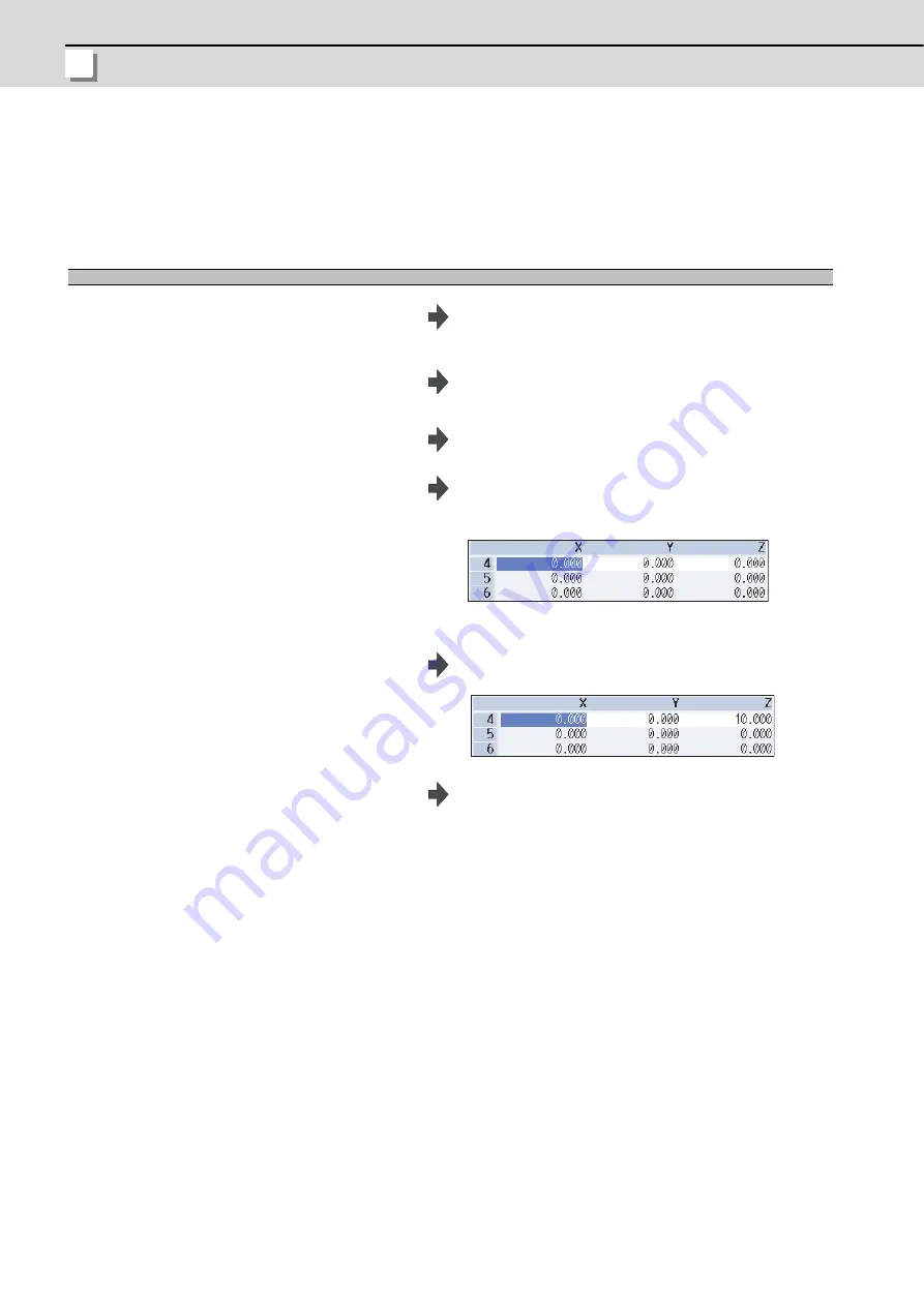
(4)
Turn the measurement switch ON.
"On meas" is displayed. Guide drawing for manual tool length
measurement II is displayed. Tool compensation data is
displayed, placing the offset No. set in "Tool No. (Tool length
measurement 2)" (PLC device) at the top.
(Note) The row at the cursor position will not be changed.
(5)
Move the additional axis in the minus direction by
manual feed and have the tool nose contact with the
touch sensor.
Measurement value is set for the additional axis of the offset
No. set in "Tool No. (Tool length measurement2)" (PLC device)
(6)
Turn the measurement switch OFF.
"On meas" disappears.
Содержание E70 Series
Страница 1: ......
Страница 3: ......
Страница 9: ......
Страница 11: ......
Страница 13: ......
Страница 15: ......
Страница 24: ...I SCREEN OPERATIONS ...
Страница 25: ......
Страница 26: ...I 1 1 Operating the Setting and Display Unit ...
Страница 57: ...1 Operating the Setting and Display Unit MITSUBISHI CNC I 32 ...
Страница 58: ...I 33 2 Monitor Screens ...
Страница 139: ...2 Monitor Screens MITSUBISHI CNC I 114 ...
Страница 140: ...I 115 3 Setup Screens ...
Страница 232: ...I 207 4 Edit Screens ...
Страница 286: ...E70 Series Instruction Manual 4 4 Program Input Output I 261 During file transmission During file setting 1 2 4 3 5 6 7 ...
Страница 314: ...I 289 5 Diagnosis Screens ...
Страница 355: ...5 Diagnosis Screens MITSUBISHI CNC I 330 ...
Страница 356: ...I 331 6 Maintenance Screens ...
Страница 436: ...II MACHINE OPERATIONS ...
Страница 437: ......
Страница 439: ...MITSUBISHI CNC II 2 ...
Страница 440: ...II 3 1 Operation State ...
Страница 444: ...II 7 2 Indicator Lamps ...
Страница 446: ...II 9 3 Reset Switch and Emergency Stop Button ...
Страница 448: ...II 11 4 Operation Mode ...
Страница 456: ...II 19 5 Operation Panel Switches in Operation Mode ...
Страница 460: ...II 23 6 Operation Panel Switch Functions ...
Страница 495: ...6 Operation Panel Switch Functions MITSUBISHI CNC II 58 ...
Страница 496: ...II 59 7 Other Functions ...
Страница 509: ...7 Other Functions MITSUBISHI CNC II 72 ...
Страница 510: ...III MAINTENANCE ...
Страница 511: ......
Страница 512: ...III 1 1 Daily Maintenance and Periodic Inspection and Maintenance ...
Страница 515: ...1 Daily Maintenance and Periodic Inspection and Maintenance MITSUBISHI CNC III 4 ...
Страница 516: ...III 5 2 Hardware Replacement Methods ...
Страница 531: ...2 Hardware Replacement Methods MITSUBISHI CNC III 20 ...
Страница 532: ...IV APPENDIXES ...
Страница 533: ......
Страница 534: ...IV 1 Appendix 1 List of Function Codes ...
Страница 536: ...IV 3 Appendix 2 Table of Command Value Ranges ...
Страница 543: ...Appendix 2 Table of Command Value Ranges MITSUBISHI CNC IV 10 ...
Страница 544: ...IV 11 Appendix 3 Circular Cutting Radius Error ...
Страница 546: ...IV 13 Appendix 4 Registering Editing the Fixed Cycle Program ...
Страница 561: ...Appendix 4 Registering Editing the Fixed Cycle Program MITSUBISHI CNC IV 28 ...
Страница 562: ...IV 29 Appendix 5 RS 232C I O Device Parameter Setting Examples ...
Страница 564: ...IV 31 Appendix 6 Explanation of Alarms ...
Страница 678: ...IV 145 Appendix 7 Operation Messages ...
Страница 699: ...Appendix 7 Operation Messages MITSUBISHI CNC IV 166 ...
Страница 700: ...IV 167 Appendix 8 User Parameters ...
Страница 777: ...Appendix 8 User Parameters MITSUBISHI CNC IV 244 ...
Страница 782: ......