Chapter
Ⅲ
Windows
251
Ⅱ
Operation
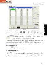
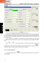
Fig. 3-48
In the figure, at the bottom of the path screen, it displays the coordinate level of the present path
and the scaling of the path graph.
In the right column, meanwhile, it displays the current absolute position coordinate and the
relative coordinate position value and the tool number used in the currently running program.
Then, the graph can be zoomed in and out and the path can be cleared, and
press
,
,
or
to move the graph up, down, right or left.
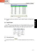
Note: The name for each axis is set by parameter #1020, and the names are set in the different letters.
3.6.3 Simulation graph
On the graph window, press
to access the simulation graph window and it is shown
as Fig.2:
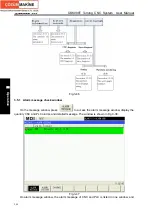
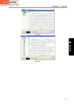
Fig. 3-49
In the figure, at the bottom of the simulation graph screen, it displays the coordinate level of the
present simulation graph and the scaling of the simulation graph.
On the simulation graph window, only the graph simulation message of XZ level is displayed.
Содержание 988T
Страница 6: ...GSK988T Turning CNC System User Manual VI ...
Страница 14: ...GSK988T Turning CNC System User Manual XIV ...
Страница 15: ...Chapter 1 Programming Fundamentals 1 Ⅰ Programming Ⅰ PROGRAMMING ...
Страница 16: ...GSK988T Turning CNC System User Manual 2 Ⅰ Programming ...
Страница 194: ...GSK988T Turning CNC System User Manual 180 Ⅰ Programming ...
Страница 195: ...Chapter Ⅰ Overview 181 Ⅱ Operation Ⅱ OPERATION ...
Страница 196: ...GSK988T Turning CNC System User Manual 182 Ⅱ Operation ...
Страница 215: ...Chapter Ⅲ Windows 201 Ⅱ Operation Note It can be displayed after U disk is inserted in the U disk catalog ...
Страница 217: ...Chapter Ⅲ Windows 203 Ⅱ Operation ...
Страница 267: ...Chapter Ⅲ Windows 253 Ⅱ Operation Fig 3 51 Fig 3 52 ...
Страница 412: ...GSK988T Turning CNC system User Manual 398 Appendix Fig 3 5 Horizontal operation panel appearance dimension ...


