GSK988T Turning CNC System User Manual
228
Ⅱ
Operation
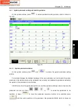
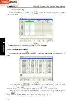
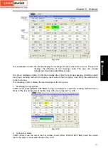
1. DC parameter setting
In PLC Value state display window, press
to enter DT parameter setting display window
shown in Fig. 3-28:
Fig. 3.-28
The setting method of DT parameter is the same that of D parameter.
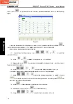
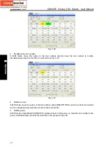
3.3.5.3 PLC state search display
In the ladder window, press
and
to enter PLC state display window shown in Fig.
3-29:
Fig. 3-29
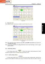
In the window, press
and the system displays the state message of X, Y, F, G. at the
moment, press
,
to switch X, Y, F, G, press
,
to view X, Y, F, G.
There is the annotation of each parameter below the window when the parameter is viewed.
Press
to view the detailed annotation of each bit of each parameter.
Содержание 988T
Страница 6: ...GSK988T Turning CNC System User Manual VI ...
Страница 14: ...GSK988T Turning CNC System User Manual XIV ...
Страница 15: ...Chapter 1 Programming Fundamentals 1 Ⅰ Programming Ⅰ PROGRAMMING ...
Страница 16: ...GSK988T Turning CNC System User Manual 2 Ⅰ Programming ...
Страница 194: ...GSK988T Turning CNC System User Manual 180 Ⅰ Programming ...
Страница 195: ...Chapter Ⅰ Overview 181 Ⅱ Operation Ⅱ OPERATION ...
Страница 196: ...GSK988T Turning CNC System User Manual 182 Ⅱ Operation ...
Страница 215: ...Chapter Ⅲ Windows 201 Ⅱ Operation Note It can be displayed after U disk is inserted in the U disk catalog ...
Страница 217: ...Chapter Ⅲ Windows 203 Ⅱ Operation ...
Страница 267: ...Chapter Ⅲ Windows 253 Ⅱ Operation Fig 3 51 Fig 3 52 ...
Страница 412: ...GSK988T Turning CNC system User Manual 398 Appendix Fig 3 5 Horizontal operation panel appearance dimension ...


