Chapter
Ⅳ
Tool Nose Radius Compensation
157
Ⅰ
Programming
Tool nose radius
center path
(
I,K
)
r
r
A
S
N2
N1
G42
G4
0
B(X,Z)
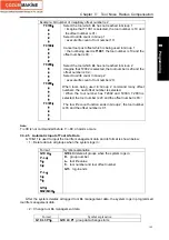
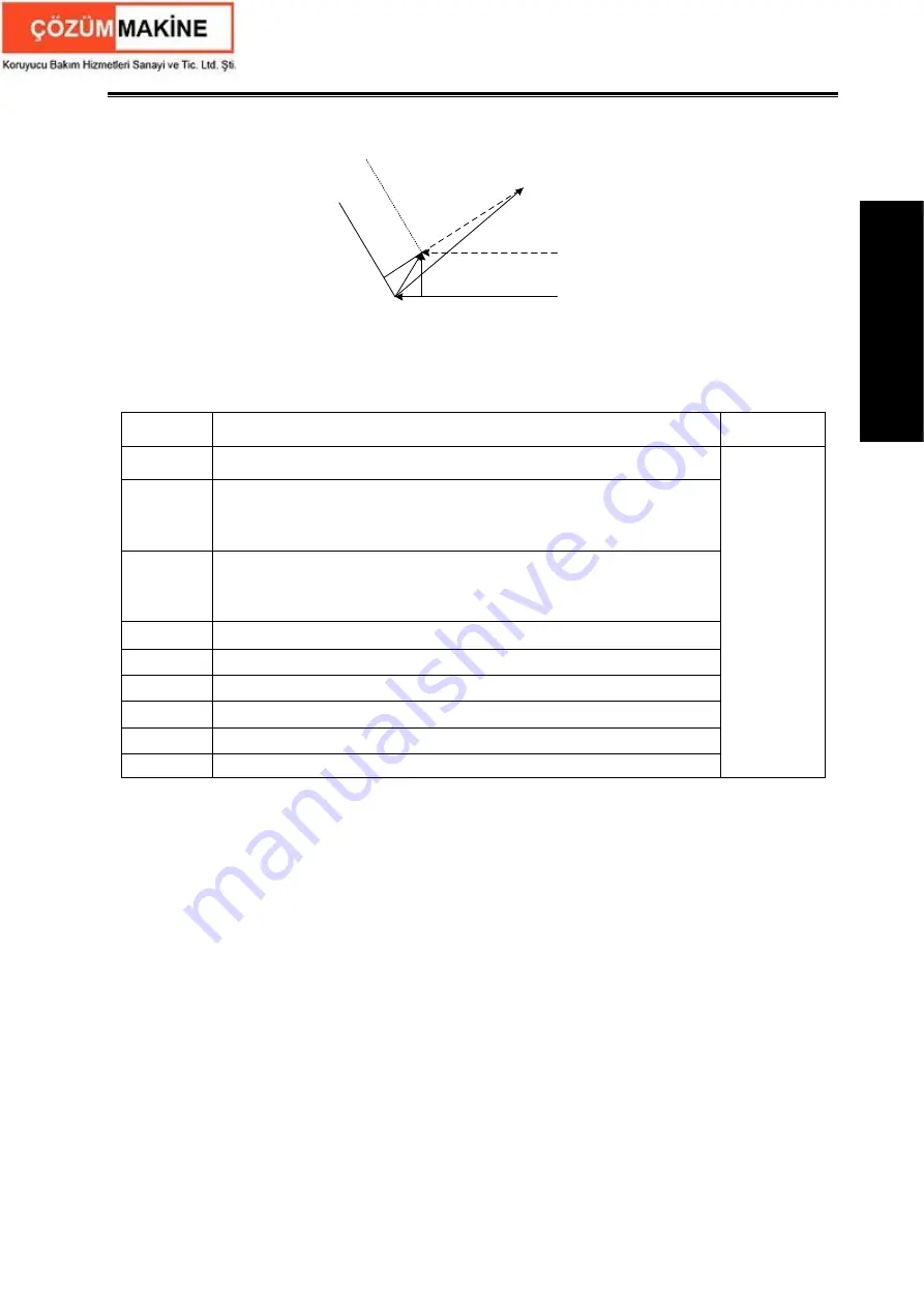
N1 G42 mode tool nose center moves to A point
N2 G40 Xp__ Zp__ I__ K__ tool nose center moves to B point
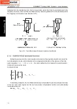
Fig. 4-11 G40 execution process
Command explanation:
Table 4-2
Commands Function
specifications
Remark
G40
Cancel the tool nose radius compensation
G41
Tool nose radius left compensation is specified by G41 in rear tool
post coordinate system and tool nose radius right compensation is
specified by G41 in front tool post coordinate system
G42
Tool nose radius right compensation is specified by G42 in rear tool
post coordinate system and tool nose radius left compensation is
specified by G42 in front tool post coordinate system
Xp
X and its parallel axis
Yp
Y and its parallel axis
Zp
Z and its parallel axis
I
X and the cancel vector (radius value) of its parallel axis
J
Y and the cancel vector (radius value) of its parallel axis
K
Z and the cancel vector (radius value) of its parallel axis
See Fig.4-11
and 4-12
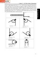
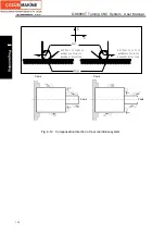
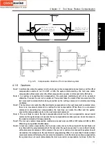
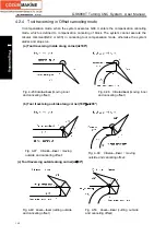
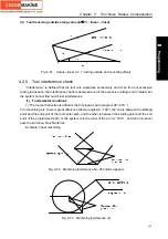
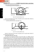
4.1.5 Compensation direction
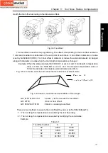
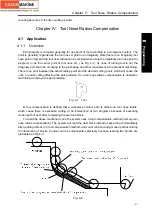
Specify its direction according to relative position between tool nose and workpiece when
executing tool nose radius compensation as Fig. 4-12 and Fig.4-13.
Содержание 988T
Страница 6: ...GSK988T Turning CNC System User Manual VI ...
Страница 14: ...GSK988T Turning CNC System User Manual XIV ...
Страница 15: ...Chapter 1 Programming Fundamentals 1 Ⅰ Programming Ⅰ PROGRAMMING ...
Страница 16: ...GSK988T Turning CNC System User Manual 2 Ⅰ Programming ...
Страница 194: ...GSK988T Turning CNC System User Manual 180 Ⅰ Programming ...
Страница 195: ...Chapter Ⅰ Overview 181 Ⅱ Operation Ⅱ OPERATION ...
Страница 196: ...GSK988T Turning CNC System User Manual 182 Ⅱ Operation ...
Страница 215: ...Chapter Ⅲ Windows 201 Ⅱ Operation Note It can be displayed after U disk is inserted in the U disk catalog ...
Страница 217: ...Chapter Ⅲ Windows 203 Ⅱ Operation ...
Страница 267: ...Chapter Ⅲ Windows 253 Ⅱ Operation Fig 3 51 Fig 3 52 ...
Страница 412: ...GSK988T Turning CNC system User Manual 398 Appendix Fig 3 5 Horizontal operation panel appearance dimension ...

