Chapter
Ⅳ
Tool Nose Radius Compensation
145
Ⅰ
Programming
modify the tool offset according to the dimension offset.
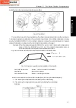
Fig.3-5 Tool offset
The tool offset is used for the programming. The offset corresponding to the tool offset number in
T command is added or subtracted on the end point of each block. X tool offset in diameter or radius
is set by No.5004 Bit1(ORC). For X tool offset in diameter or radius, the external diameter is changed
along with diameter or radius when the tool length compensation is changed.
Example: When the state parameter No.5004 Bit1 is set to 0 and X tool length compensation
value is 10mm, No.5004 Bit1 is set to 1 and X tool length compensation value is
10mm the diameter of workpiece external diameter is 20mm.
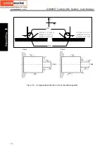
Fig. 3-6 is to create, execute and cancel the tool offset in movement mode.
Fig. 3-6 Creation, execution and cancellation of tool length
G01 X100 Z100 T0101
;
(
Block 1, start to execute the tool offset
)
G01 W150
;
(
Block 2, tool offset
)
G01 X50 Z300 T0100
;
(
Block 3, canceling tool offset
)
There are two methods to execute the tool offset(they are set by No.5002 Bit4(LGT)):
(
1
)
The tool length compensation is executed by the tool traversing;
(
2
)
The tool length compensation is executed by modifying the coordinates;
Example:
Table 3-1
Tool offset number
X
Z
00 0.000
0.000
01 0.000
0.000
02 12.000
-23.000
03 24.560
13.452
Содержание 988T
Страница 6: ...GSK988T Turning CNC System User Manual VI ...
Страница 14: ...GSK988T Turning CNC System User Manual XIV ...
Страница 15: ...Chapter 1 Programming Fundamentals 1 Ⅰ Programming Ⅰ PROGRAMMING ...
Страница 16: ...GSK988T Turning CNC System User Manual 2 Ⅰ Programming ...
Страница 194: ...GSK988T Turning CNC System User Manual 180 Ⅰ Programming ...
Страница 195: ...Chapter Ⅰ Overview 181 Ⅱ Operation Ⅱ OPERATION ...
Страница 196: ...GSK988T Turning CNC System User Manual 182 Ⅱ Operation ...
Страница 215: ...Chapter Ⅲ Windows 201 Ⅱ Operation Note It can be displayed after U disk is inserted in the U disk catalog ...
Страница 217: ...Chapter Ⅲ Windows 203 Ⅱ Operation ...
Страница 267: ...Chapter Ⅲ Windows 253 Ⅱ Operation Fig 3 51 Fig 3 52 ...
Страница 412: ...GSK988T Turning CNC system User Manual 398 Appendix Fig 3 5 Horizontal operation panel appearance dimension ...


