Chapter
Ⅶ
Tool Offset and Setting Tools
289
Ⅱ
Operation
Fig.7-9
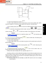
12. The tool cuts along face A1 as Fig.7-9;
13. When Z axis remains still, the tool retracts along X axis and the spindle stops rotation;
measure the distance “
β
” from face A1 to the origin of the work piece coordinate system;
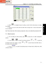
14.On the setting window, press
to access the tool offset management window, and press
to select the corresponding tool offset number, and press
or
to select the
window, and press
or
to select the tool offset or the wearing value to be rewritten;
15. Press
to access the measuring window, input
and measuring value
β
in
ˊ
; After pressing
, Z axis tool offset value or its wearing value
is set in the corresponding offset number;
16. The tool cuts along face B1;
17. When X axis remains still, the tool retracts along Z axis and the spindle stops revolving; 18.
Measure distance “
α
”;
ˊ
19. Press
to access the measuring window, input
and the measuring value
α
in
ˊ
, and then press
and X axis tool offset value or its
wearing value is set in the corresponding offset number;
20.About the method of setting other tools, repeat the steps of 10
~
19.
Measuring method is to set the differential value between the tool reference position (such as the
tool nose position) and the actual tool nose position during processing as the tool offset value. For
example: when the coordinate value of face B is 50.0, the actual measured value is
α
=49.0, then the
tool offset value in X direction is 1.0.
Note: After the machine zero return toolsetting is executed, G50 cannot be used to set a workpiece
coordinate system.
Содержание 988T
Страница 6: ...GSK988T Turning CNC System User Manual VI ...
Страница 14: ...GSK988T Turning CNC System User Manual XIV ...
Страница 15: ...Chapter 1 Programming Fundamentals 1 Ⅰ Programming Ⅰ PROGRAMMING ...
Страница 16: ...GSK988T Turning CNC System User Manual 2 Ⅰ Programming ...
Страница 194: ...GSK988T Turning CNC System User Manual 180 Ⅰ Programming ...
Страница 195: ...Chapter Ⅰ Overview 181 Ⅱ Operation Ⅱ OPERATION ...
Страница 196: ...GSK988T Turning CNC System User Manual 182 Ⅱ Operation ...
Страница 215: ...Chapter Ⅲ Windows 201 Ⅱ Operation Note It can be displayed after U disk is inserted in the U disk catalog ...
Страница 217: ...Chapter Ⅲ Windows 203 Ⅱ Operation ...
Страница 267: ...Chapter Ⅲ Windows 253 Ⅱ Operation Fig 3 51 Fig 3 52 ...
Страница 412: ...GSK988T Turning CNC system User Manual 398 Appendix Fig 3 5 Horizontal operation panel appearance dimension ...

