GSK988T Turning CNC System User Manual
106
Ⅰ
Programming
speed(r/min). If the spindle speed varies, the actual feedrate changes
too. If the spindle cutting feed amount per rev is specified by G99
FXXXX , the even cutting texture on the surface of workpiece will be
gotten. In G99 state, a spindle encoder should be fixed on the machine
tool to machine the workpiece.
F range in G98, G99 is shown below.
Address Incremental system
Metric
(
mm
)
input
Inch (inch)input
ISB system
1~
60000 mm/min
0.01
~
2400 inch/min
F
(
G98
)
ISC system
1~
24000 mm/min
0.01
~
960 inch/min
ISB system
0.01
~
500mm/r 0.01
~
9.99inch/r
F
(
G99
)
ISC system
0.01
~
500mm/r 0.01
~
9.99 inch/r
Reduction formula of feed between per rev and per min:
F
m
= F
r
×S
F
m
: feed per min (mm/min) ;
F
r
: feed per rev(mm/r) ;
S: spindle speed (r/min) .
F value is reserved after the system executes F command.
Note 1: G98, G99 are the modal G commands in the same group and only one is valid. G98 is the initial
state G command and the system defaults the modal can be set by No.3402 Bit4 (FPM) when the
system turns on.
Note 2: In G99 modal, there is the uneven cutting feed rate when the spindle speed is lower than 1 r/min;
there is the follow error in the actual cutting feed rate when there is the swing in the spindle speed.
To gain the high machining quality, it is recommended that the selected spindle speed should be
not lower than min. speed of spindle servo or converter.
Note 3: No.1422 set the upper of the cutting feedrate. When the actual cutting feedrate (the value is
multiplied by the override) exceeds the specified upper limit, it is clamped to the upper limit value.
Note 4: No. 1403 Bit0(MIF)can set the cutting speed unit per minute and the detailed is referred to the
parameter explanation.
Note 5: When G99 instead of F command in G98 mode is commanded, F is the previous modal value in
G99. In a similar way, when G98 instead of F command in G99 mode is commanded, F is the
previous modal value in G98.
Note 6: When the initial mode is G98/99, and G99/G98 is alone executed after power on, the system runs at
the speed set by No. 1411.
2.19 Drilling/Boring Fixed Cycle Command
Many blocks completes one machining in the course of drilling. To simplify programming,
GSK988T uses one drilling cycle G commands to complete a series of drilling machining. (C tool
compensation vector in the course of drilling/boring will temporarily cancel, automatically recovers
after the command is completed)
z
Execution
process
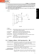
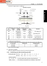
The drilling fixed cycle is composed of the following 6 operations.
Operation 1: X(Z) and C axis (requirement in some occasion) positions to the hole positon of
initial level;
Operation 2: rapidly traverse to point R;
Operation 3: drilling (cutting feed or interval feed);
Operation 4: pause at the hole bottom;
Operation 5: retract tool to the level where point R is;
Содержание 988T
Страница 6: ...GSK988T Turning CNC System User Manual VI ...
Страница 14: ...GSK988T Turning CNC System User Manual XIV ...
Страница 15: ...Chapter 1 Programming Fundamentals 1 Ⅰ Programming Ⅰ PROGRAMMING ...
Страница 16: ...GSK988T Turning CNC System User Manual 2 Ⅰ Programming ...
Страница 194: ...GSK988T Turning CNC System User Manual 180 Ⅰ Programming ...
Страница 195: ...Chapter Ⅰ Overview 181 Ⅱ Operation Ⅱ OPERATION ...
Страница 196: ...GSK988T Turning CNC System User Manual 182 Ⅱ Operation ...
Страница 215: ...Chapter Ⅲ Windows 201 Ⅱ Operation Note It can be displayed after U disk is inserted in the U disk catalog ...
Страница 217: ...Chapter Ⅲ Windows 203 Ⅱ Operation ...
Страница 267: ...Chapter Ⅲ Windows 253 Ⅱ Operation Fig 3 51 Fig 3 52 ...
Страница 412: ...GSK988T Turning CNC system User Manual 398 Appendix Fig 3 5 Horizontal operation panel appearance dimension ...

