Chapter
Ⅱ
G Commands
43
Ⅰ
Programming
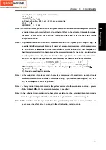
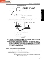
together execute interpolation, which is taken as the interpolation of Z-X level coordinate system
in G18 level.
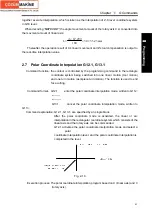
When decoding “
N07 C30.0”
, the angle movement amount of the rotary axis C si converted into
the movment amount of linear axis:
67.299
30 35.23
180
L
mm
π
×
=
×
=
Thereafter, the operation result of C‘s linear movement and Z’s tool compensation is output to
the real-time interpolation value
2.7 Polar Coordinate Interpolation G12.1, G13.1
Command function: the contour is controlled by the programming command in the rectangle
coordinate system being switched into one linear motion (tool motion)
and one turn motion (workpiece turn motion). The function is used to end
face cutting.
Command format
:
G12.1
;
enter the polar coordinate interpolation mode, written to G112;
---------
;
----------
;
G13.1
;
cancel the polar coordinate interpolation mode, written to
G113;
Command explanation: G12.1, G13.1, are specified by an single block.
After the polar coordinate mode is activated, the linear or arc
interpolation in the rectangular coordinate system which consists of the
linear axis and the rotary axis can be commanded.
G12.1 activates the polar coordinate interpolation mode and select a
polar
coordinate interpolation level, and the polar coordinate interpolation is
completed in the level.
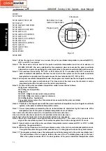
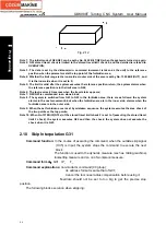
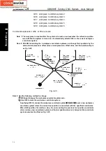
Fig. 2-10
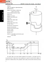
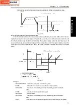
Execution process: The polar coordinate interpolation program based on X (linear axis) and C
(rotary axis).
Содержание 988T
Страница 6: ...GSK988T Turning CNC System User Manual VI ...
Страница 14: ...GSK988T Turning CNC System User Manual XIV ...
Страница 15: ...Chapter 1 Programming Fundamentals 1 Ⅰ Programming Ⅰ PROGRAMMING ...
Страница 16: ...GSK988T Turning CNC System User Manual 2 Ⅰ Programming ...
Страница 194: ...GSK988T Turning CNC System User Manual 180 Ⅰ Programming ...
Страница 195: ...Chapter Ⅰ Overview 181 Ⅱ Operation Ⅱ OPERATION ...
Страница 196: ...GSK988T Turning CNC System User Manual 182 Ⅱ Operation ...
Страница 215: ...Chapter Ⅲ Windows 201 Ⅱ Operation Note It can be displayed after U disk is inserted in the U disk catalog ...
Страница 217: ...Chapter Ⅲ Windows 203 Ⅱ Operation ...
Страница 267: ...Chapter Ⅲ Windows 253 Ⅱ Operation Fig 3 51 Fig 3 52 ...
Страница 412: ...GSK988T Turning CNC system User Manual 398 Appendix Fig 3 5 Horizontal operation panel appearance dimension ...


