GSK988T Turning CNC System User Manual
44
Ⅰ
Programming
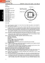
O0001
;
N10 T0202
…
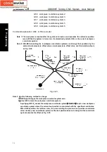
N100 G00 X150 C0 Z0
;
N110 G12.1
;
N120 G42 G01 X80 F200;
N130 C20;
N140 G03 X40 C40 R20;
N150 G01 X-40;
N160 G03 X-80 C20 R20;
N170 G01 C-20;
N180 G03 X-40 C-40 R20;
N190 G01 X40;
N200 G03 X80 C-20 R20;
N210 G01 C0;
N220 G40 X150.0;
N230 G13.1;
N240 Z100.0
…
N500 M30
Note 1: When the system is turned on or resets, the polar coordinate interpolation is cancelled(G13.1);
G12.1 and G13.1 are modal;
Note 2: The linear axis and turn axis for the polar coordinate interpolation must be set in advance in
NO.5460, NO.5461; the axis undefined by the parameter does not execute the polar coordinate
interpolation in spite of specifying the movement value in the polar coordinate interpolation mode;
Note 3: The used level (selected by G17, G18 or G19) before G12.1 is cancelled; after G13.1 cancels the
polar coordinate interpolation, the level recovers; when the system resets, the polar coordinate
interpolation is cancelled and the system uses the level selected by G17, G18 or G19;
Note 4: In the polar coordinate interpolation mode, the program commands use the rectangular coordinate
command in the polar coordinate level. The linear axis in the level uses the diameter or radius
programming and the turn axis uses the radius programming;
Note 5: G codes in the polar coordinate interpolation mode can be used as follows:
G01
:
linear interpolation;
G02, G03
:
arc interpolation;
G04
:
dwell;
G40, G41, G42
:
tool nose radius compensation;
G65, G66, G67
:
user macro program command;
G98, G99
:
feed/rev, feed/minute;
The system alarms when other G commands are executed in the polar coordinate
interpolation mode.
Note 6: F feedrate is the tangent speed with the polar coordinate interpolation level(rectangular coordinate
system) in the polar coordinate interpolation mode;
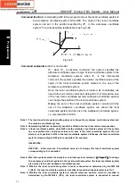
Note 7: The arc interpolation commanding the arc radius address is determined by the linear axis of the
interpolation level in the polar coordinate interpolation level as follows:
Use I and J when the linear axis is X or its parallel and the turn axis uses J;
Use J and K when the linear axis is X or its parallel and the turn axis uses J;
Use K and I when the linear axis is Z or its parallel and the turn axis uses I;
Note 8: Must set a workpiece coordinate system before using G12.1, the center of the turn axis is the
origin of the coordinate system. The coordinate system must not be changed in G12.1 mode.
Note 9: Cannot start or cancel the polar coordinate interpolation mode; command G12.1 or G13.1 in G40;
otherwise, the system alarms;
Note 10: When the tool traverses near to the workpiece center in the polar coordinate interpolation mode,
C weight of feedrate changes, which exceeds max. C cutting speed to cause the system alarms.
Note 11: The program command uses the rectangular coordinate command in the polar coordinate level.
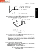
The axis address of the turn axis is taken as the one of the 2
nd
axis(imaginary axis) in the level.
When the system executes G12.1, the tool position of the polar coordinate interpolation starts
X
Program path
Virtual axis
C
Path after tool nose
radius compensation
N120
N130
N140
N150
N160
N170
N180
N190
N200
N210
Fig.2-11
Содержание 988T
Страница 6: ...GSK988T Turning CNC System User Manual VI ...
Страница 14: ...GSK988T Turning CNC System User Manual XIV ...
Страница 15: ...Chapter 1 Programming Fundamentals 1 Ⅰ Programming Ⅰ PROGRAMMING ...
Страница 16: ...GSK988T Turning CNC System User Manual 2 Ⅰ Programming ...
Страница 194: ...GSK988T Turning CNC System User Manual 180 Ⅰ Programming ...
Страница 195: ...Chapter Ⅰ Overview 181 Ⅱ Operation Ⅱ OPERATION ...
Страница 196: ...GSK988T Turning CNC System User Manual 182 Ⅱ Operation ...
Страница 215: ...Chapter Ⅲ Windows 201 Ⅱ Operation Note It can be displayed after U disk is inserted in the U disk catalog ...
Страница 217: ...Chapter Ⅲ Windows 203 Ⅱ Operation ...
Страница 267: ...Chapter Ⅲ Windows 253 Ⅱ Operation Fig 3 51 Fig 3 52 ...
Страница 412: ...GSK988T Turning CNC system User Manual 398 Appendix Fig 3 5 Horizontal operation panel appearance dimension ...


