Chapter
Ⅰ
Overview
191
Ⅱ
Operation
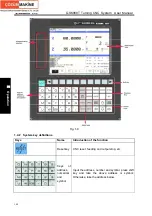
Fig.1-10
Note: The operations related to the machine operation panel described in the manual has two types, and when
the panel allocated by the user is different from the two, please refer to the attached message.
1.5.2 State indicator and press key definition on the panel
The function of keys on GSK988T machine panel is defined by PLC program (ladder diagram),
and about the detailed function of each key, refer to the manual of the machine manufacturer. The
machine panel is taken as the reference.
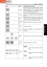
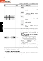
Function of the machine panel each key defined by GSK988T standard PLC program, refer to
the following list:
State indication
The indicator
for each axis
reference
position
return
Running indicator
Alarm
indicator
Self-defined indicator
Gear/tool
number
indicator
Press key definition:
Keys
Names
Function
Mode during valid
function
Содержание 988T
Страница 6: ...GSK988T Turning CNC System User Manual VI ...
Страница 14: ...GSK988T Turning CNC System User Manual XIV ...
Страница 15: ...Chapter 1 Programming Fundamentals 1 Ⅰ Programming Ⅰ PROGRAMMING ...
Страница 16: ...GSK988T Turning CNC System User Manual 2 Ⅰ Programming ...
Страница 194: ...GSK988T Turning CNC System User Manual 180 Ⅰ Programming ...
Страница 195: ...Chapter Ⅰ Overview 181 Ⅱ Operation Ⅱ OPERATION ...
Страница 196: ...GSK988T Turning CNC System User Manual 182 Ⅱ Operation ...
Страница 215: ...Chapter Ⅲ Windows 201 Ⅱ Operation Note It can be displayed after U disk is inserted in the U disk catalog ...
Страница 217: ...Chapter Ⅲ Windows 203 Ⅱ Operation ...
Страница 267: ...Chapter Ⅲ Windows 253 Ⅱ Operation Fig 3 51 Fig 3 52 ...
Страница 412: ...GSK988T Turning CNC system User Manual 398 Appendix Fig 3 5 Horizontal operation panel appearance dimension ...


