Chapter
Ⅱ
G Commands
45
Ⅰ
Programming
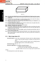
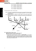
from the angle 0. So, the spindle must be positioned before the polar coordinate interpolation is
executed.
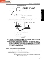
Note 12: The current position displays the actual coordinates in the polar coordinate interpolation.
However, the remainder distance is displayed according to the coordinates in the polar
coordinate interpolation level(rectangular coordinate level).
Note 13: Must not switch the spindle gear in the polar coordinate interpolation. The system must be in the
spindle speed control mode when the gear shifting is needed.
2.8 Metric/Inch Switch G20, G21
Command function: realize the metric/inch switch of the system input mode.
Command format: G20; inch input
G21; metric input
Command explanation: G20/G21 is modal in Group 6, and can be set to the initial mode by
No.0000 BIT2 (INI);
G20/G21
The units of the following value will change after they switch between the metric and the inch.
——F feedrate;
——position command;
——zero offset of workpiece;
——tool compensation value;
——scale unit of MPG;
——movement in incremental feed.
Note 1: The initial mode of G20/G21 is set by NO. 0000 BIT2 (INI) when the system is turned on.
Note 2: When G20/G21 switches the current input mode, the system must set the beginning of the
program and specify in an alone block, otherwise, the system alarms.
Note 3: The tool compensation value must input the incremental unit and set it again. The tool
compensation value can automatically change and cannot be set again when NO.5006 Bit0 is 1.
Note 4: It modifies NO.0000 Bit2 (INI) when the system executes G20/G21. the displayed mode also
changes when NO.0000 Bit 2 (INI) is changed.
2.9 Stored Travel Check G22, G23
Command function:
Create the forbidden area of stored travel limit check 2 and limit the tool
traverse range in one area.
Command format
:
G22
;
stored travel 2 check is turned on
---------
;
---------
;
G23
;
stored travel 2 check is turned off
Command explanation: G22: stored travel check is turned on;
G23: stored travel check is turned off;
Positive coordinates of the stored travel area is set by No.1322;
Negative coordinates of the stored travel area is set by No. 1323;
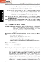
Limit area figure: taking examples of X, Y, Z limit area are as follows. X, Y, Z are positive
coordinates, I, J, K are negative.
Содержание 988T
Страница 6: ...GSK988T Turning CNC System User Manual VI ...
Страница 14: ...GSK988T Turning CNC System User Manual XIV ...
Страница 15: ...Chapter 1 Programming Fundamentals 1 Ⅰ Programming Ⅰ PROGRAMMING ...
Страница 16: ...GSK988T Turning CNC System User Manual 2 Ⅰ Programming ...
Страница 194: ...GSK988T Turning CNC System User Manual 180 Ⅰ Programming ...
Страница 195: ...Chapter Ⅰ Overview 181 Ⅱ Operation Ⅱ OPERATION ...
Страница 196: ...GSK988T Turning CNC System User Manual 182 Ⅱ Operation ...
Страница 215: ...Chapter Ⅲ Windows 201 Ⅱ Operation Note It can be displayed after U disk is inserted in the U disk catalog ...
Страница 217: ...Chapter Ⅲ Windows 203 Ⅱ Operation ...
Страница 267: ...Chapter Ⅲ Windows 253 Ⅱ Operation Fig 3 51 Fig 3 52 ...
Страница 412: ...GSK988T Turning CNC system User Manual 398 Appendix Fig 3 5 Horizontal operation panel appearance dimension ...


