Chapter
Ⅱ
G Commands
51
Ⅰ
Programming
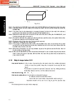
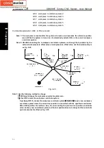
Fig. 2-19
Note 1: After the system is turned on, it does not execute the manual reference position return; when the
system executes G28 reference position return, it judges it alarms or executes like the manual
reference position return according to No. 1002 Bit 3(AZR) to use the deceleration block to
execute the reference position return. But, when the reference position setting function without
the block(No.1002 Bit1 (DLZ)) is set to 1 or NO.1005 Bit 1(DLZx) is set to 1, it is unrelated to AZR
setting, the system alarms when the system executes G28 before the reference position is
created.
Note 2: Each axis separately moves at the rapid traverse speed from the starting point through the middle
point to the reference position, i.e. G00 mode.
Note 3: G28 or G30 in the tool radius compensation mode automatically cancels the tool radius
compensation, and automatically recovers it in the next movement command.
Note 4: Generally, G28 is specified in an alone line; when the system specifies simultaneously the same
parameter address word of G00 or G01, IP_ is specified to G28 parameter, G00 or G01 only change
the modal value of the corresponding G groups and does not execute the motion.
2.12.2 2
nd
, 3
rd
, 4
th
reference position return G30
Command function:
move at the rapidly traverse speed to the middle point specified IP_ and
then to the 2
nd
, 3
rd
and 4
th
reference position.
Command format
:
G30 P2 IP__
;
return to the 2
nd
reference position
G30 P3 IP__
;
return to the 3
rd
reference position
G30 P4 IP__
;
return to the 4
th
reference position
Command explanation:
G30 is non-modal;
IP_: it is the middle point coordinates, is specified by the absolute value and
incremental value. Omit one or all command address for each axis, omitting some
axis means the axis does not return to the reference position, omitting all means
the middle point is the tool starting point in the current workpiece coordinate
system, and the tool does not return to the reference position and keeps stopping.
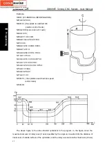
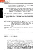
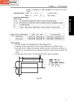
Command execution process (as Fig.2-18):
(
1
)
Rapidly position from the current position to the middle position of the command
axis(A
→
B);
(
2
)
Rapidly position from the middle point to the reference position (B
→
R);
Note 1: Reference position position is set in NO.1241
~
NO.1243;
Note 2: After the system is turned on, it executes the reference position return once before executing G30;
do not execute the reference position return firstly before executing G30 after the system with the
absolute encoder is turned on;
Note 3: When P is omitted, the system executes it as P2 and returns to the 2
nd
reference position;
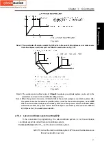
Note 4: The middle point will move to the new workpiece coordinate system when the workpiece
Содержание 988T
Страница 6: ...GSK988T Turning CNC System User Manual VI ...
Страница 14: ...GSK988T Turning CNC System User Manual XIV ...
Страница 15: ...Chapter 1 Programming Fundamentals 1 Ⅰ Programming Ⅰ PROGRAMMING ...
Страница 16: ...GSK988T Turning CNC System User Manual 2 Ⅰ Programming ...
Страница 194: ...GSK988T Turning CNC System User Manual 180 Ⅰ Programming ...
Страница 195: ...Chapter Ⅰ Overview 181 Ⅱ Operation Ⅱ OPERATION ...
Страница 196: ...GSK988T Turning CNC System User Manual 182 Ⅱ Operation ...
Страница 215: ...Chapter Ⅲ Windows 201 Ⅱ Operation Note It can be displayed after U disk is inserted in the U disk catalog ...
Страница 217: ...Chapter Ⅲ Windows 203 Ⅱ Operation ...
Страница 267: ...Chapter Ⅲ Windows 253 Ⅱ Operation Fig 3 51 Fig 3 52 ...
Страница 412: ...GSK988T Turning CNC system User Manual 398 Appendix Fig 3 5 Horizontal operation panel appearance dimension ...


