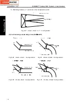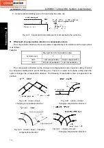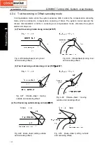
Chapter
Ⅳ
Tool Nose Radius Compensation
153
Ⅰ
Programming
direction in cutting. Suppose there are 10
(
T0
~
T9
)
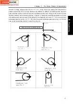
kinds of tool nose setting and 9 directions for
position relationship. The tool nose directions are different in different coordinate system (rear tool
post coordinate system and front tool post coordinate system) even if they are the same tool nose
direction numbers as the following figures. In figures, it represents relationships between tool nose
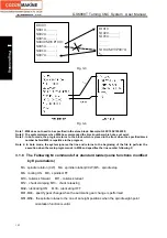
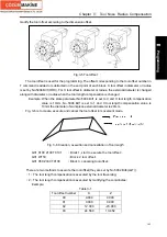
and starting point, and end point of arrowhead is the imaginary tool nose; T1
~
T8 in rear tool post
coordinate system is as Fig. 4-7; T1
~
T8 in front tool post coordinate system is as Fig. 4-8. The tool
nose center and starting point for T0 and T9 as Fig. 4-9.
Z axis
X axis
I m a g i n a r y t o o l
n o s e N o . 1
Imaginary tool
nose No. 2
Imaginary tool
nose No.3
Imaginary tool
nose No.4
Imaginary tool
nose No.5
Imaginary tool
nose No.6
Rear tool post coordinate system
Содержание 988T
Страница 6: ...GSK988T Turning CNC System User Manual VI ...
Страница 14: ...GSK988T Turning CNC System User Manual XIV ...
Страница 15: ...Chapter 1 Programming Fundamentals 1 Ⅰ Programming Ⅰ PROGRAMMING ...
Страница 16: ...GSK988T Turning CNC System User Manual 2 Ⅰ Programming ...
Страница 194: ...GSK988T Turning CNC System User Manual 180 Ⅰ Programming ...
Страница 195: ...Chapter Ⅰ Overview 181 Ⅱ Operation Ⅱ OPERATION ...
Страница 196: ...GSK988T Turning CNC System User Manual 182 Ⅱ Operation ...
Страница 215: ...Chapter Ⅲ Windows 201 Ⅱ Operation Note It can be displayed after U disk is inserted in the U disk catalog ...
Страница 217: ...Chapter Ⅲ Windows 203 Ⅱ Operation ...
Страница 267: ...Chapter Ⅲ Windows 253 Ⅱ Operation Fig 3 51 Fig 3 52 ...
Страница 412: ...GSK988T Turning CNC system User Manual 398 Appendix Fig 3 5 Horizontal operation panel appearance dimension ...


