Chapter
Ⅱ
G Commands
79
Ⅰ
Programming
roughing, and Z cutting direction is opposite to the sign symbol of
Δ
k:
Δ
k
>
0, cut in
Z negative direction in roughing. It is reserved after
Δ
k command value is
executed and the system rewrites No.5136 value. NO.5136 value is regarded as
the travel of X tool retraction of roughing when W
(
Δ
k
)
is not input.
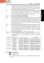
d
It is the cutting times and its range is referred to the following table. R5 means the
closed cutting cycle is completed by 5 times cutting. R
(
d
)
is reserved after it is
executed and the system rewrites NO.5137. The value of system parameter
NO.5137 is regarded as the cutting times when R
(
d is not input.
ns
Block number of the first block of finishing path.
nf
Block number of the last block of finishing path.
Δ
u
It is X finishing allowance as the following table (diameter value with sign
symbols ) and is the X coordinate offset of roughing contour compared to finishing
path, i.e. the different value of X absolute coordinates of A
1
compared to A.
Δ
u
>
0
,
it is the offset of the last X positive roughing path compared to finishing path. The
system defaults
Δ
u=0 when U
(
Δ
u
)
is not input, i.e. there is no X finishing
allowance for roughing cycle.
Δ
w
It is Z finishing allowance as the following table -99.999~99.999 (unit: mm ) and is
the Z coordinate offset of roughing contour compared to finishing path, i.e. the
different value of Z absolute coordinate of A
1
compared to A.
Δ
w
>
0
,
it is the offset
of the last roughing path compared to finishing path in Z positive direction. The
system defaults
Δ
w=0 when W
(
Δ
w
)
is not input, i.e. there is no Z finishing
allowance for roughing cycle.
F
Feedrate; S: Spindle speed; T: Tool number, tool offset number.
M, S, T, F
They can be specified in the first G73 or the second ones or program ns
~
nf. M, S,
T, F functions of M, S, T, F blocks are invalid in G73, and they are valid in G70
finishing blocks.
Address Incremental
system
Metric
(
mm
)
input
Inch (inch) input
ISB system
-99999.999
~
99999.999 mm
-9999.9999
~
9999.9999 inch
U
(
Δ
i
)
ISC system
-9999.9999
~
9999.9999 mm
-999.99999
~
999.99999 inch
ISB system
-99999.999
~
99999.999 mm
-9999.9999
~
9999.9999 inch
W
(
Δ
k
)
ISC system
-9999.9999
~
9999.9999 mm
-999.99999
~
999.99999 inch
R
(
d
)
ISB, ISC
1
~
999
(
times
)
1
~
999
(
times
)
ISB system
-99999.999
~
99999.999 mm
-9999.9999
~
9999.9999 inch
U (
Δ
u
)
ISC system
-9999.9999
~
9999.9999 mm
-999.99999
~
999.99999 inch
ISB system
-99999.999
~
99999.999 mm
-9999.9999
~
9999.9999 inch
W
(
Δ
w
)
ISC system
-9999.9999
~
9999.9999 mm
-999.99999
~
999.99999 inch
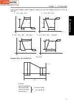
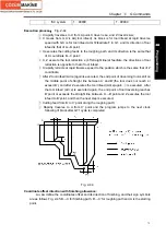
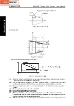
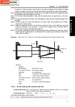
Execution process:(Fig. 2-40).
①
A
→
A
1
:
Rapid traverse
;
②
First roughing A
1
→
B
1
→
C
1
:
A
1
→
B
1
:
Rapid traverse speed in ns block in G0, cutting feedrate specified by G73 in ns
block in G1
;
Содержание 988T
Страница 6: ...GSK988T Turning CNC System User Manual VI ...
Страница 14: ...GSK988T Turning CNC System User Manual XIV ...
Страница 15: ...Chapter 1 Programming Fundamentals 1 Ⅰ Programming Ⅰ PROGRAMMING ...
Страница 16: ...GSK988T Turning CNC System User Manual 2 Ⅰ Programming ...
Страница 194: ...GSK988T Turning CNC System User Manual 180 Ⅰ Programming ...
Страница 195: ...Chapter Ⅰ Overview 181 Ⅱ Operation Ⅱ OPERATION ...
Страница 196: ...GSK988T Turning CNC System User Manual 182 Ⅱ Operation ...
Страница 215: ...Chapter Ⅲ Windows 201 Ⅱ Operation Note It can be displayed after U disk is inserted in the U disk catalog ...
Страница 217: ...Chapter Ⅲ Windows 203 Ⅱ Operation ...
Страница 267: ...Chapter Ⅲ Windows 253 Ⅱ Operation Fig 3 51 Fig 3 52 ...
Страница 412: ...GSK988T Turning CNC system User Manual 398 Appendix Fig 3 5 Horizontal operation panel appearance dimension ...

