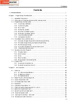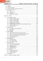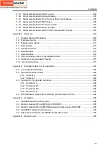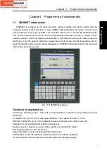
Contents
IX
3.1.2 End of program run M30.......................................................................................139
3.1.3 Program stop M00 ................................................................................................139
3.1.4 Optional stop M01.................................................................................................140
3.1.5 Subprogram call M98 .........................................................................................140
3.1.6 Subprogram Call M198.........................................................................................141
3.1.7 Return from Subprogram M99............................................................................141
3.1.8 The Following M commands for standard ladder(some functions modified by K
parameters) ......................................................................................................................142
3.1.9 M Commands defined by standard PLC ladder ....................................................143
3.2 Spindle Function .............................................................................................................143
3.2.1 Spindle speed analog voltage control ...................................................................143
3.2.2 Spindle override ....................................................................................................144
3.3 Tool Function ..................................................................................................................144
3.3.1 Tool offset .............................................................................................................144
3.3.2 Tool Life Management ..........................................................................................147
Chapter IV Tool Nose Radius Compensation...............................................................................151
4.1 Application ......................................................................................................................151
4.1.1 Overview...............................................................................................................151
4.1.2 Imaginary tool nose direction ................................................................................152
4.1.3 Compensation value setting..................................................................................155
4.1.4 G40/G41/G42 command function .........................................................................156
4.1.5 Compensation direction ........................................................................................157
4.1.6 Cautions ...............................................................................................................159
4.1.7 Application ............................................................................................................160
4.2 Tool Nose Radius Compensation Offset Path.................................................................161
4.2.1 Inner and outer side..............................................................................................161
4.2.2 Tool traversing when starting tool .........................................................................161
4.2.3 Tool traversing in Offset mode ..............................................................................163
4.2.4 Tool traversing in Offset canceling mode ..............................................................168
4.2.5 Tool interference check.........................................................................................169
4.2.6 Commands for canceling compensation vector temporarily .................................171
4.2.7 Particulars.............................................................................................................174
Ⅱ
OPERATION
...........................................................................................................................181
Chapter
Ⅰ
Overview.....................................................................................................................183
1.1 Operation Overview ........................................................................................................183
1.2 System Setting................................................................................................................184
1.3 Display ............................................................................................................................185
1.4 System............................................................................................................................187
1.4.1 System panel ........................................................................................................187
1.4.2 System key definitions ..........................................................................................188
1.5 Machine Operation Panel ...............................................................................................190
1.5.1 Division of machine operation panel .....................................................................190
1.5.2 State indicator and press key definition on the panel............................................191
Chapter
Ⅱ
Power on, Power off and Safety Protection ................................................................196
Содержание 988T
Страница 6: ...GSK988T Turning CNC System User Manual VI ...
Страница 14: ...GSK988T Turning CNC System User Manual XIV ...
Страница 15: ...Chapter 1 Programming Fundamentals 1 Ⅰ Programming Ⅰ PROGRAMMING ...
Страница 16: ...GSK988T Turning CNC System User Manual 2 Ⅰ Programming ...
Страница 194: ...GSK988T Turning CNC System User Manual 180 Ⅰ Programming ...
Страница 195: ...Chapter Ⅰ Overview 181 Ⅱ Operation Ⅱ OPERATION ...
Страница 196: ...GSK988T Turning CNC System User Manual 182 Ⅱ Operation ...
Страница 215: ...Chapter Ⅲ Windows 201 Ⅱ Operation Note It can be displayed after U disk is inserted in the U disk catalog ...
Страница 217: ...Chapter Ⅲ Windows 203 Ⅱ Operation ...
Страница 267: ...Chapter Ⅲ Windows 253 Ⅱ Operation Fig 3 51 Fig 3 52 ...
Страница 412: ...GSK988T Turning CNC system User Manual 398 Appendix Fig 3 5 Horizontal operation panel appearance dimension ...


