Chapter
Ⅲ
Windows
245
Ⅱ
Operation
servo of X, Z, S axis.
Note: The servo diagnosis can display normally only when the system’s servo communication function is
valid, each servo system is connected correctly and the allocation of the servo slave number is correct.
3.5.4 Oscillograph window
Press
to enter the message window and press to enter the oscillograph window. Before
the oscillograph is used, the user must set the monitored servo Value, the oscillograph monitor type,
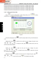
the wave zoom unit and the triggered sampling time. The oscillograph setting window is shown in Fig.
3-42:
Fig.3-42
The detailed explanation of the setting content is shown below:
(
1
)
“CH1”,“CH2”:select the communication to be set.
(
2
)
Monitor mode: set the oscillograph to be the trigger or the memory. The trigger: it the
sampling mode is that the above setting sampling realizes the arrival time stop sampling
mode. The memory: the sampling mode is that the sampling is stopped after the system
has checked the servo alarm.
The difference of the two monitor modes are shown below:
Attribute
Type
Sampling start mode
Sample end mode
Waveform
Value
saved?
Trigger
Press start/stop soft key Automatically stops after
sampling time ends
No
Memory
Press start/stop soft
key
Automatically stop
when the servo alarms
Automatically save
(
3
)
Sampling period. The sampling period of GSK-CAN communication function is within
Содержание 988T
Страница 6: ...GSK988T Turning CNC System User Manual VI ...
Страница 14: ...GSK988T Turning CNC System User Manual XIV ...
Страница 15: ...Chapter 1 Programming Fundamentals 1 Ⅰ Programming Ⅰ PROGRAMMING ...
Страница 16: ...GSK988T Turning CNC System User Manual 2 Ⅰ Programming ...
Страница 194: ...GSK988T Turning CNC System User Manual 180 Ⅰ Programming ...
Страница 195: ...Chapter Ⅰ Overview 181 Ⅱ Operation Ⅱ OPERATION ...
Страница 196: ...GSK988T Turning CNC System User Manual 182 Ⅱ Operation ...
Страница 215: ...Chapter Ⅲ Windows 201 Ⅱ Operation Note It can be displayed after U disk is inserted in the U disk catalog ...
Страница 217: ...Chapter Ⅲ Windows 203 Ⅱ Operation ...
Страница 267: ...Chapter Ⅲ Windows 253 Ⅱ Operation Fig 3 51 Fig 3 52 ...
Страница 412: ...GSK988T Turning CNC system User Manual 398 Appendix Fig 3 5 Horizontal operation panel appearance dimension ...

