GSK988T Turning CNC System User Manual
250
Ⅱ
Operation
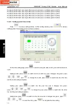
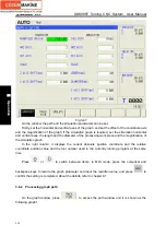
Fig.3-47
On the window, the path and the simulation parameters can be set.
Firstly, set the horizontal and vertical axes of the graph, and set the offset of the coordinate axis
and the magnification of the graph; if the simulation graph is required, set the simulation horizontal
and vertical axes, the length and the diameter of the processing work piece and the magnification of
the simulation graph.
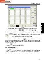
In the right column, it displays the current absolute position coordinate and the relative
coordinate position value and the tool number used in the currently running program at the same
time.
Press
or
to switch between items; in MDI mode, press the numerical and
backspace keys to rewrite the graph parameter and input the rewritten value, and press
to
confirm the setting is completed. About the details, refer to chapter 8.1.
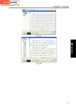
3.6.2 Processing graph path
On the graph window, press
to access the path window and it is shown as the
following graph 1:
Содержание 988T
Страница 6: ...GSK988T Turning CNC System User Manual VI ...
Страница 14: ...GSK988T Turning CNC System User Manual XIV ...
Страница 15: ...Chapter 1 Programming Fundamentals 1 Ⅰ Programming Ⅰ PROGRAMMING ...
Страница 16: ...GSK988T Turning CNC System User Manual 2 Ⅰ Programming ...
Страница 194: ...GSK988T Turning CNC System User Manual 180 Ⅰ Programming ...
Страница 195: ...Chapter Ⅰ Overview 181 Ⅱ Operation Ⅱ OPERATION ...
Страница 196: ...GSK988T Turning CNC System User Manual 182 Ⅱ Operation ...
Страница 215: ...Chapter Ⅲ Windows 201 Ⅱ Operation Note It can be displayed after U disk is inserted in the U disk catalog ...
Страница 217: ...Chapter Ⅲ Windows 203 Ⅱ Operation ...
Страница 267: ...Chapter Ⅲ Windows 253 Ⅱ Operation Fig 3 51 Fig 3 52 ...
Страница 412: ...GSK988T Turning CNC system User Manual 398 Appendix Fig 3 5 Horizontal operation panel appearance dimension ...

