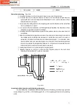
Chapter
Ⅱ
G Commands
83
Ⅰ
Programming
executed end point of current path.
7. G70 cannot be executed in MDI mode, otherwise, the system alarms.
2.15.5 Axial Grooving Multiple Cycle G74
Command function:
Axial (X) tool infeed cycle compounds radial discontinuous cutting cycle:
Tool infeeds from starting point in radial direction(Z), retracts, infeeds
again, and again and again, and last tool retracts in axial direction, and
retracts to the Z position in radial direction, which is called one radial
cutting cycle; tool infeeds in axial direction and execute the next radial
cutting cycle; cut to end point of cutting, and then return to starting
point (starting point and end point are the same one in G74), which is
called one radial grooving compound cycle. Directions of axial tool
infeed and radial tool infeed are defined by relative position between
end point X
(
U
)
Z
(
W
)
and starting point of cutting. The command is
used to machine radial loop groove or column surface by radial
discontinuously cutting, breaking stock and stock removal.
Command format
:
G74 R
(
e
);
G74 X
(
U
)
Z
(
W
)
P
(
Δ
i
)
Q
(
Δ
k
)
R
(
Δ
d
)
F
;
Command specifications
:
(
1
)
The cycle movement is executed by Z
(
W
)
and P
(
Δ
k
)
blocks of G74, and the movement
is not executed if only “G74 R
(
e
);
” block is executed;
(
2
)
Δ
d and e are specified by the same address and whether there are Z
(
W
)
and P
(
Δ
k
)
word or not in blocks to distinguish them;
(
3
)
The tool can stop in Auto mode and traverse in Manual mode when G74 is executed, but
the tool must return to the position before executing in Manual mode when G74 is
executed again, otherwise the following path will be wrong.
(
4
)
When the single block is running, programs pauses after each axial cutting cycle is
completed.
(
5
)
R
(
Δ
d
)
must be omitted in blind hole cutting, and so there is no distance of tool retraction
when the tool cuts to axial end point
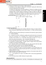
Relevant definitions
:
Starting point
of axial cutting
cycle
Starting position of axial tool infeed for each axial cutting cycle, defining with
A
n
(n=1,2,3……), Z coordinate of A
n
is the same that of starting point A,
the different
value of X coordinate between A
n
and A
n-1
is
Δ
i. The starting point A
1
of the first
axial cutting cycle is the same as the starting point A, and the X coordinate of starting
point (A
f
) of the last axial cutting cycle is the same that of cutting end point.
End point of
axial tool
infeed
Starting position of axial tool infeed for each axial cutting cycle, defining with
B
n
(n=1,2,3……), Z coordinate of B
n
is the same that of cutting end point,
X coordinate
of B
n
is the same that of A
n
, and the end point (B
f
) of the last axial tool infeed is the
same that of cutting end point.
End point of
radius tool
retraction
End
position of radius tool infeed(travel of tool infeed is
Δ
d) after each axial cutting
cycle reaches the end point of axial tool infeed, defining with C
n
(n=1,2,3……), Z
coordinate of C
n
is the same that of cutting end point, and the different value of X
Содержание 988T
Страница 6: ...GSK988T Turning CNC System User Manual VI ...
Страница 14: ...GSK988T Turning CNC System User Manual XIV ...
Страница 15: ...Chapter 1 Programming Fundamentals 1 Ⅰ Programming Ⅰ PROGRAMMING ...
Страница 16: ...GSK988T Turning CNC System User Manual 2 Ⅰ Programming ...
Страница 194: ...GSK988T Turning CNC System User Manual 180 Ⅰ Programming ...
Страница 195: ...Chapter Ⅰ Overview 181 Ⅱ Operation Ⅱ OPERATION ...
Страница 196: ...GSK988T Turning CNC System User Manual 182 Ⅱ Operation ...
Страница 215: ...Chapter Ⅲ Windows 201 Ⅱ Operation Note It can be displayed after U disk is inserted in the U disk catalog ...
Страница 217: ...Chapter Ⅲ Windows 203 Ⅱ Operation ...
Страница 267: ...Chapter Ⅲ Windows 253 Ⅱ Operation Fig 3 51 Fig 3 52 ...
Страница 412: ...GSK988T Turning CNC system User Manual 398 Appendix Fig 3 5 Horizontal operation panel appearance dimension ...


