Configuring a WAN Routing Service
Page 29-60
Step 2. Set Up a Frame Relay Routing Service
You create a Frame Relay routing service using the
cas
command. Follow the steps below to
set up a routing service.
1.
Enter the
cas
command followed the slot number, a slash (/), the port number, and then
the service number for the routing service:
cas 2/3 1
A screen similar to the following displays:
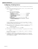
Slot 1 Port 2 Service 3 Configuration
1) Description ................................................................... = Frame-Relay
{Enter up to 30 characters}
2) Service Type ................................................................. = Bridging
{(T)runking, (R)outing, (B)ridging}
3) Administrative Status .................................................... = Enabled
{(E)nable, (D)isable}
4) VC(s)............................................................................. = 0
5) VLAN Group(s) .............................................................. = 0
6) Frame-Relay Bridging Mode (Applies to Bridging Only).. = Bridge All
{Bridge (a)ll, (E)thernet only}
(save/quit/cancel)
:
You make changes to the options in this screen at the colon prompt (:). You make
changes by entering the line number for the option you want to change, an equal sign
(=), and then the value for the new parameter.
2.
Enter a description of this routing service by entering 1, an equal sign (=), and then a
description for this service. Your description can be up to 30 characters long.
1=<router service name>
When you are done entering a description, press
<Enter>
.
3.
Specify that this is a routing service by entering a 2, an equal sign, and an
R
as follows:
2=5
This specifies that you want to set up a routing service, as opposed to a Trunking or
Bridging service. Press
<Enter>
.
4.
By default, the routing service is Enabled. This means that as soon as you are done
configuring the service, it will begin routing Frame Relay traffic. If you would like to
disable this routing service now and enable it later, enter
3=D
and press
<Enter>
.
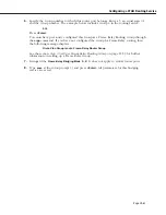
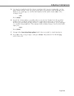
5.
You need to specify the
DLCI
s of the virtual circuits to include in this routing service.
Multiple VCs may be configured for a single routing service and all configured VCs will
map to a single virtual router port. Enter a 4, an equal sign (=), and then the
DLCI
numbers for each virtual circuit. Separate
DLCI
s with spaces, as shown in the example
below.
4=16 17
Press
<Enter>
after you enter all virtual circuit
DLCI
s.
Содержание Omni Switch/Router
Страница 1: ...Part No 060166 10 Rev C March 2005 Omni Switch Router User Manual Release 4 5 www alcatel com ...
Страница 4: ...page iv ...
Страница 110: ...WAN Modules Page 3 40 ...
Страница 156: ...UI Table Filtering Using Search and Filter Commands Page 4 46 ...
Страница 164: ...Using ZMODEM Page 5 8 ...
Страница 186: ...Displaying and Setting the Swap State Page 6 22 ...
Страница 202: ...Creating a New File System Page 7 16 ...
Страница 270: ...Displaying Secure Access Entries in the MPM Log Page 10 14 ...
Страница 430: ...OmniChannel Page 15 16 ...
Страница 496: ...Configuring Source Route to Transparent Bridging Page 17 48 ...
Страница 542: ...Dissimilar LAN Switching Capabilities Page 18 46 ...
Страница 646: ...Application Example DHCP Policies Page 20 30 ...
Страница 660: ...GMAP Page 21 14 ...
Страница 710: ...Viewing the Virtual Interface of Multicast VLANs Page 23 16 ...
Страница 722: ...Application Example 5 Page 24 12 ...
Страница 788: ...Viewing UDP Relay Statistics Page 26 24 ...
Страница 872: ...The WAN Port Software Menu Page 28 46 ...
Страница 960: ...Deleting a PPP Entity Page 30 22 ...
Страница 978: ...Displaying Link Status Page 31 18 ...
Страница 988: ...Displaying ISDN Configuration Entry Status Page 32 10 ...
Страница 1024: ...Backup Services Commands Page 34 14 ...
Страница 1062: ...Diagnostic Test Cable Schematics Page 36 24 ...
Страница 1072: ...Configuring a Switch with an MPX Page A 10 ...
Страница 1086: ...Page B 14 ...
Страница 1100: ...Page I 14 Index ...

