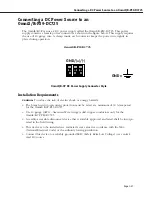
Connecting a DC Power Source to an OmniS/R-PS9-DC725
Page 1-28
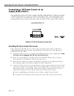
Installing DC Power Source Wire Leads
These instructions describe how to connect your 3-wire DC power source to the power
connector on your DC power supply. A small flat-tip screwdriver and a wire stripper are
required for this procedure.
1.
Prepare the three (3) wires—10 gauge—that will plug into the power supply. First,
make
sure they are not plugged into the 48-volt power source.
2.
Next, use a wire stripper to carefully strip about a half-inch off the end of each wire,
removing the outer insulation to expose the copper core.
3.
Twist the loose strands of copper wire together so that they form a tight braid. If possi-
ble, solder the entire braid of wire together for better conductivity.
4.
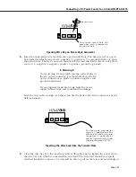
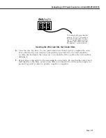
Open the wire bay door for one of the three (3) power connector holes. The front of the
power connector contains a row of square holes. It also contains three (3) circular holes
(located directly above the square holes) that contain screws; you loosen the screws in
these holes to open the wire bay doors (square holes) on the connector front so that you
can insert the wire leads into the power connector.
a.
Insert a small flat-tip screwdriver into one of the three (3) screw holes.
b.
Loosen the screw so that the door for the wire bay on the connector front opens.
Opening Wire Bay on DC Power Supply Connector
5.
Insert the appropriate wire lead into the open circular hole. The silkscreen above each
hole indicates which power lead—ground (GND), positive (+), or negative (-)—to plug
into which hole. The lead you insert
must
match the lead attached to the 48-volt power
source (i.e., ground to ground, positive to positive, negative to negative).
♦
Warning
♦
You
must
plug DC wire leads into the correct holes in
the DC power connector. Use the labels above the DC
power connector as a guide to ground, positive and
negative connections.
If you plug wire leads into the wrong holes, the power
supply will not work and could result in damage.
Push the wire in far enough so that it reaches the back wall of the connector, about a half
inch inside.
Door inside square hole will
open when screw is loosened in
circular hole directly above it.
Loosen Screw.
GND/(+)/(-)
Содержание Omni Switch/Router
Страница 1: ...Part No 060166 10 Rev C March 2005 Omni Switch Router User Manual Release 4 5 www alcatel com ...
Страница 4: ...page iv ...
Страница 110: ...WAN Modules Page 3 40 ...
Страница 156: ...UI Table Filtering Using Search and Filter Commands Page 4 46 ...
Страница 164: ...Using ZMODEM Page 5 8 ...
Страница 186: ...Displaying and Setting the Swap State Page 6 22 ...
Страница 202: ...Creating a New File System Page 7 16 ...
Страница 270: ...Displaying Secure Access Entries in the MPM Log Page 10 14 ...
Страница 430: ...OmniChannel Page 15 16 ...
Страница 496: ...Configuring Source Route to Transparent Bridging Page 17 48 ...
Страница 542: ...Dissimilar LAN Switching Capabilities Page 18 46 ...
Страница 646: ...Application Example DHCP Policies Page 20 30 ...
Страница 660: ...GMAP Page 21 14 ...
Страница 710: ...Viewing the Virtual Interface of Multicast VLANs Page 23 16 ...
Страница 722: ...Application Example 5 Page 24 12 ...
Страница 788: ...Viewing UDP Relay Statistics Page 26 24 ...
Страница 872: ...The WAN Port Software Menu Page 28 46 ...
Страница 960: ...Deleting a PPP Entity Page 30 22 ...
Страница 978: ...Displaying Link Status Page 31 18 ...
Страница 988: ...Displaying ISDN Configuration Entry Status Page 32 10 ...
Страница 1024: ...Backup Services Commands Page 34 14 ...
Страница 1062: ...Diagnostic Test Cable Schematics Page 36 24 ...
Страница 1072: ...Configuring a Switch with an MPX Page A 10 ...
Страница 1086: ...Page B 14 ...
Страница 1100: ...Page I 14 Index ...

