Application Example 4
Page 24-8
Application Example 4
Routing in
IPX
Networks
How Routing Works Generally
AutoTracker “activates” a
VLAN
– and its internal router interface – when the first port is
assigned to the
VLAN
. If a
VLAN
has a port policy, AutoTracker assigns the specified port(s)
and activates the
VLAN
immediately. If a
VLAN
has a logical policy, AutoTracker assigns the
first port to the
VLAN
when a frame is received from a source device that matches the
VLAN
’s
policy. When such a frame is received, the source device – and the port to which that device
is connected – are assigned to the
VLAN
and the
VLAN
is activated.
Until a port is assigned to a
VLAN
, that
VLAN
is maintained in an inactive state and its internal
router port is inactive – even if routing was enabled by the user. Use of a
VLAN
’s routing
service is “on-demand” and AutoTracker does not enable routing until a port is present that
might require it. When AutoTracker assigns the first port to a particular
VLAN
, it activates that
VLAN
and its routing service (as long as routing was enabled by the user).
Once AutoTracker has established devices’
VLAN
assignments and activated the appropriate
VLAN
routing services, it does not participate in the routing process. Routing works correctly
as long as the policies of the
IPX
protocol were followed – with the exception below.
The Exception
There is one scenario in which AutoTracker affects the behavior of an
IPX
-routed network.
This situation occurs when an
IPX
server is a member of any
VLAN
with
IPX
network address
policies
and
IPX
routing is enabled on the Group’s default
VLAN
#1. An exception condition
arises in this situation because all ports in a Group are always members of that Group’s default
VLAN
#1 in addition to any other
VLAN
s of which they are members. As a result, default
VLAN
#1 is always active.
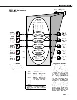
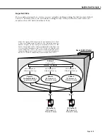
The figure on the facing page illustrates this problem situation. In this figure, three
VLAN
s
within Group 2 – one of which is default
VLAN
#1 – have
IPX
routing enabled, as indicated by
the presence of the internal
IPX
router.
VLAN
s 2 and 3 both have
IPX
network address poli-
cies. When
IPX
Server A is connected to the Omni Switch/Router on port 1, the Server is
assigned to
VLAN
2 (per the network address policy) and port 1 becomes a member of
VLAN
2. When
IPX
Server B is connected to the Omni Switch/Router on port 2, the Server is
assigned to
VLAN
3 (per the network address policy) and port 2 becomes a member of
VLAN
3. However, ports 1 and 2 are also members of the Group’s default
VLAN
#1, so port 1 is now
a member of
VLAN
1 and
VLAN
2 and port 2 is now a member of
VLAN
1 and
VLAN
3.
When
IPX
Server A sends broadcasts, they are restricted to
VLAN
2 because of the network
address policies. When
IPX
Server B sends broadcasts, they are restricted to
VLAN
3, also
because of the network address policies. However, when the internal
IPX
router sends out
broadcasts on
VLAN
1 the broadcasts are flooded out all ports in the Group, because all ports
in the Group are, by default, members of
VLAN
1.
IPX
Server A responds to this with a router
configuration error because it is receiving broadcasts on
VLAN
1 when it should only receive
them on
VLAN
2.
IPX
Server B also responds with a router configuration error because it is
receiving broadcasts on
VLAN
1 when it should only receive them on
VLAN
3.
The Solution
The solution for this problem is to disable
IPX
routing on default
VLAN
#1. Because of this,
when your network includes
IPX
servers that are members of
IPX
network address
VLAN
s and
IPX
routing is enabled, you should configure your network such that disabling
IPX
routing on
default
VLAN
#1 is not a problem.
Содержание Omni Switch/Router
Страница 1: ...Part No 060166 10 Rev C March 2005 Omni Switch Router User Manual Release 4 5 www alcatel com ...
Страница 4: ...page iv ...
Страница 110: ...WAN Modules Page 3 40 ...
Страница 156: ...UI Table Filtering Using Search and Filter Commands Page 4 46 ...
Страница 164: ...Using ZMODEM Page 5 8 ...
Страница 186: ...Displaying and Setting the Swap State Page 6 22 ...
Страница 202: ...Creating a New File System Page 7 16 ...
Страница 270: ...Displaying Secure Access Entries in the MPM Log Page 10 14 ...
Страница 430: ...OmniChannel Page 15 16 ...
Страница 496: ...Configuring Source Route to Transparent Bridging Page 17 48 ...
Страница 542: ...Dissimilar LAN Switching Capabilities Page 18 46 ...
Страница 646: ...Application Example DHCP Policies Page 20 30 ...
Страница 660: ...GMAP Page 21 14 ...
Страница 710: ...Viewing the Virtual Interface of Multicast VLANs Page 23 16 ...
Страница 722: ...Application Example 5 Page 24 12 ...
Страница 788: ...Viewing UDP Relay Statistics Page 26 24 ...
Страница 872: ...The WAN Port Software Menu Page 28 46 ...
Страница 960: ...Deleting a PPP Entity Page 30 22 ...
Страница 978: ...Displaying Link Status Page 31 18 ...
Страница 988: ...Displaying ISDN Configuration Entry Status Page 32 10 ...
Страница 1024: ...Backup Services Commands Page 34 14 ...
Страница 1062: ...Diagnostic Test Cable Schematics Page 36 24 ...
Страница 1072: ...Configuring a Switch with an MPX Page A 10 ...
Страница 1086: ...Page B 14 ...
Страница 1100: ...Page I 14 Index ...

