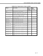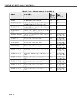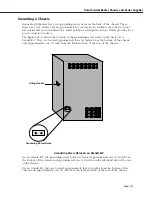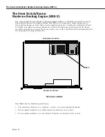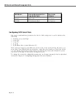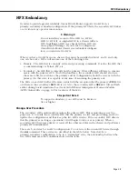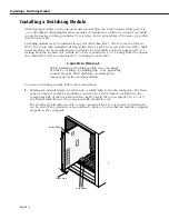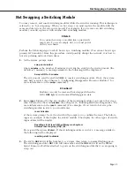
Omni Switch/Router Management Processor Module (MPX) Features
Page 2-2
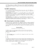
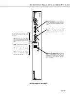
Omni Switch/Router Management Processor Module (MPX) Status LEDs
MPX 10 mm
MODEM
CONSOLE
PRI
SEC
TEMP
PS1
PS2
OK2
OK1
ACT
COL
LINK
ETHERNET
OK1
(Hardware Status). This dual-
state
LED
is on Green when the MPX
has passed power-on hardware diag-
nostics successfully. On Amber when
the hardware has failed diagnostic
tests. If the
OK1
LED
is alternating
Green and Amber, then file system
compaction is in progress.
Caution
Do not power down the Omni
Switch/Router or insert any
modules while the
OK1
LED
is
alternating Green and Amber.
If you do, file corruption may
result and you will not be able
to restart the switch.
OK2
(Software Status). Blinking Green
when the MPX has successfully load-
ed software to the switching modules.
Blinking Amber when the MPX is in a
transitional state, such as when it first
boots up. If the
O K 2
L E D
blinks
Amber for an extended period of time
(i.e., more than a minute), then you
should reboot the switch.
Caution
Do not insert or remove any
modules while the MPX
OK2
LED
is blinking Amber. If you
do, file corruption may result
and you will not be able to
restart the switch.
Module
Status
LEDs
PRI
(Primary MPX). On Green
when this MPX is the active, or
controlling, MPX. It is also on
Green when this is the only MPX
installed in the switch.
SEC
(Secondary MPX). On Green
when this MPX is the secondary
MPX in a redundant MPX config-
uration. As the secondary MPX,
this module is in hot standby
mode.
TEMP
(Temperature). On Yel-
low to warn that the internal
switch temperature is approach-
ing maximum operating limits.
Note that this
LED
comes on
before
the temperature limit is
reached.
PS1
(Power Supply 1 Status).
This dual-state
LED
is on Green
when the switch is receiving the
proper voltage from Power Sup-
p l y 1 . I t i s o n A m b e r w h e n
Power Supply 1 is on, but not
supplying the correct amount of
voltage to power the switch, or is
installed and turned off. The
PS1
LED
is Off when the Power Sup-
ply 1 is not present.
PS2
(Power Supply 2 Status).
This dual-state
LED
is on Green
when the Omni Switch/Router is
receiving the proper voltage from
Power Supply 2. It is on Amber
when Power Supply 2 is on, but
not supplying the correct amount
of voltage to power the switch,
or is installed and turned off. The
PS2
LED
is Off when Power Sup-
ply 2 is not present.
Module
Status
LEDs
Warning Label
. This label indicates
that the module contains an optical
transceiver (on the MPXs with fiber
ST Ethernet ports only).
CLASS 1 LASER PRODUCT
Label
. This label will indicate the
Ethernet management port type. It
will read either
MPX 10 mm
(
multimo-
de fiber Ethernet port
) or
MPX 10
(cop-
per RJ-45 Ethernet port).
TX
RX
Содержание Omni Switch/Router
Страница 1: ...Part No 060166 10 Rev C March 2005 Omni Switch Router User Manual Release 4 5 www alcatel com ...
Страница 4: ...page iv ...
Страница 110: ...WAN Modules Page 3 40 ...
Страница 156: ...UI Table Filtering Using Search and Filter Commands Page 4 46 ...
Страница 164: ...Using ZMODEM Page 5 8 ...
Страница 186: ...Displaying and Setting the Swap State Page 6 22 ...
Страница 202: ...Creating a New File System Page 7 16 ...
Страница 270: ...Displaying Secure Access Entries in the MPM Log Page 10 14 ...
Страница 430: ...OmniChannel Page 15 16 ...
Страница 496: ...Configuring Source Route to Transparent Bridging Page 17 48 ...
Страница 542: ...Dissimilar LAN Switching Capabilities Page 18 46 ...
Страница 646: ...Application Example DHCP Policies Page 20 30 ...
Страница 660: ...GMAP Page 21 14 ...
Страница 710: ...Viewing the Virtual Interface of Multicast VLANs Page 23 16 ...
Страница 722: ...Application Example 5 Page 24 12 ...
Страница 788: ...Viewing UDP Relay Statistics Page 26 24 ...
Страница 872: ...The WAN Port Software Menu Page 28 46 ...
Страница 960: ...Deleting a PPP Entity Page 30 22 ...
Страница 978: ...Displaying Link Status Page 31 18 ...
Страница 988: ...Displaying ISDN Configuration Entry Status Page 32 10 ...
Страница 1024: ...Backup Services Commands Page 34 14 ...
Страница 1062: ...Diagnostic Test Cable Schematics Page 36 24 ...
Страница 1072: ...Configuring a Switch with an MPX Page A 10 ...
Страница 1086: ...Page B 14 ...
Страница 1100: ...Page I 14 Index ...


