7.10 Peripheral Devices and Options
YASKAWA
SIEPYAIH6B01A HV600 AC Drive Bypass Technical Reference
551
3.
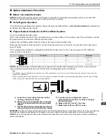
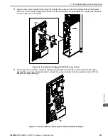
Use the two screws included in the option kit to fasten the option card to the metal standoffs on the bypass
PCB. Use a short-shaft, magnetic screwdriver for narrow enclosure models H6BPxxxx. Tighten each screw to
0.5 to 0.6 N•m (4.4 to 5.3 in lbs).
Figure 7.6 Insert Option into Bypass PCB CN5 Connector Port
4.
Firmly insert the end of the customer-supplied network cable into the CN1 connection port on the option
board. When you have a dual-port option, connect two network cables to the two network ports in CN1 for
flexibility in cabling topology.
Figure 7.7 Connect Network Cable to Option (SI-W3 LonWorks Example)
CN5
Summary of Contents for H6B1A002
Page 12: ...12 YASKAWA SIEPYAIH6B01A HV600 AC Drive Bypass Technical Reference...
Page 74: ...Page Intentionally Blank...
Page 76: ...Page Intentionally Blank...
Page 454: ...5 14 Z Bypass Parameters 454 YASKAWA SIEPYAIH6B01A HV600 AC Drive Bypass Technical Reference...
Page 590: ...8 6 Storage Guidelines 590 YASKAWA SIEPYAIH6B01A HV600 AC Drive Bypass Technical Reference...
Page 780: ...11 3 European Standards 780 YASKAWA SIEPYAIH6B01A HV600 AC Drive Bypass Technical Reference...

