YASKAWA
SIEPYAIH6B01A HV600 AC Drive Bypass Technical Reference
107
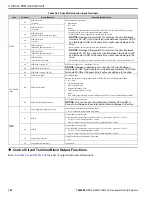
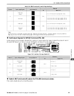
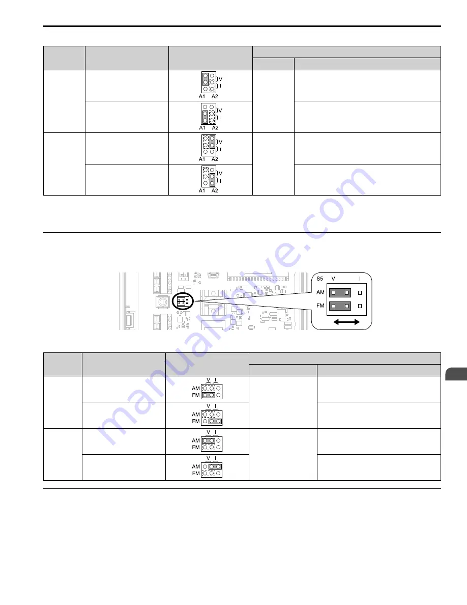
Table 3.26 MFAI Terminals A1 and A2 Signal Settings
Terminal
Types of Input Signals
Jumper Switch S1
Parameter
No.
Signal Level
A1
Voltage input
(Default)
H3-01
0: 0 V to 10 V/0% to 100% (input impedance: 20 kΩ)
Current input
2: 4 mA to 20 mA/0% to 100% (input impedance: 250 Ω)
3: 0 mA to 20 mA/0% to 100% (input impedance: 250 Ω)
A2
Voltage input
H3-09
0: 0 V to 10 V/0% to 100% (input impedance: 20 kΩ)
Current input
(Default)
2: 4 mA to 20 mA/0% to 100% (input impedance: 250 Ω)
3: 0 mA to 20 mA/0% to 100% (input impedance: 250 Ω)
Note:
Set
H3-02, H3-10 = 0 [Terminal A1 Function Selection, Terminal A2 Function Selection = Frequency Reference]
to set A1 and A2 to
frequency reference. The drive will add the analog input values together to make the frequency reference.
◆
Set Output Signals for MFAO Terminals FM, AM
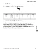
Set the signal type for terminals AM and FM to voltage or current output. Use jumper switch S5 and
H4-07, H4-08
[Terminal FM Signal Level Select, Terminal AM Signal Level Select]
to set the signal type.
Figure 3.22 Location of Jumper Switch S5
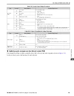
Terminal
Types of Output Signals
Jumper Switch S5
Parameter
No.
Signal Level
FM
Voltage output
(Default)
H4-07
0: 0 V to 10 V
Current output
2: 4 mA to 20 mA
AM
Voltage output
(Default)
H4-08
0: 0 V to 10 V
Current output
2: 4 mA to 20 mA
◆
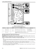
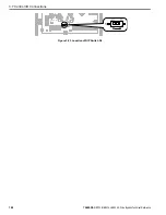
Switch ON Termination Resistor for RS-485 Communications
This switch should always be in the ON position.
Summary of Contents for H6B1A002
Page 12: ...12 YASKAWA SIEPYAIH6B01A HV600 AC Drive Bypass Technical Reference...
Page 74: ...Page Intentionally Blank...
Page 76: ...Page Intentionally Blank...
Page 454: ...5 14 Z Bypass Parameters 454 YASKAWA SIEPYAIH6B01A HV600 AC Drive Bypass Technical Reference...
Page 590: ...8 6 Storage Guidelines 590 YASKAWA SIEPYAIH6B01A HV600 AC Drive Bypass Technical Reference...
Page 780: ...11 3 European Standards 780 YASKAWA SIEPYAIH6B01A HV600 AC Drive Bypass Technical Reference...

