422
YASKAWA
SIEPYAIH6B01A HV600 AC Drive Bypass Technical Reference
drive will regulate based on the PI Aux Level and the pressure will decrease. The drive also goes to sleep, wakes up,
and detects an alarm and/or fault based on the PI Auxiliary Control level.
■
Enable PI Aux Level Control Features
Set
YF-01 = 1 [PI Aux Control Selection = Enabled]
to enable PI Aux Level Control and PI Aux Low Level
Detection.
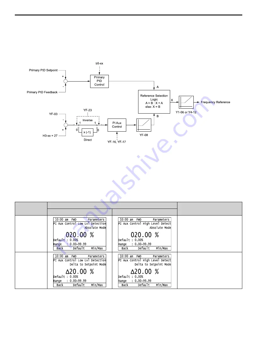
shows the primary PID and PI Auxiliary Control Diagram when
YF-01 = 1
.
b5-xx: PID Control
H3-xx = 27: PI Auxiliary Control Feedback
Y1-06: Minimum Speed
Y4-12: Thrust Frequency
YF-03: PI Aux Control Setpoint
YF-08: PI Aux Control Minimum Speed
YF-16: PI Auxiliary Control P Gain
YF-17: PI Auxiliary Control I Time
YF-23: PI Aux Ctrl Output Level Select
Figure 5.98 Primary PID and PI Auxiliary Control Diagram
■
High PI Auxiliary Feedback Level Detection
Table 5.69 Absolute Mode and Delta to Setpoint Mode
Entry Mode
Keypad Display
Description
YF-09
YF-12
Absolute
The values set for
YF-09 and YF-12
represent the
feedback level that will cause a Low PI Auxiliary
Feedback and High PI Auxiliary Feedback. You
can set these parameters as an absolute value.
Delta to Setpoint
When the left-most digit changes to a Δ (delta),
you can set the Low Feedback Level and High
Feedback Level relative to the setpoint.
The effective Low PI Auxiliary Feedback Level is
“
Setpoint -
YF-09
”
, and the effective High PI
Auxiliary Feedback Level is
“
Se
YF-12
”
.
Summary of Contents for H6B1A002
Page 12: ...12 YASKAWA SIEPYAIH6B01A HV600 AC Drive Bypass Technical Reference...
Page 74: ...Page Intentionally Blank...
Page 76: ...Page Intentionally Blank...
Page 454: ...5 14 Z Bypass Parameters 454 YASKAWA SIEPYAIH6B01A HV600 AC Drive Bypass Technical Reference...
Page 590: ...8 6 Storage Guidelines 590 YASKAWA SIEPYAIH6B01A HV600 AC Drive Bypass Technical Reference...
Page 780: ...11 3 European Standards 780 YASKAWA SIEPYAIH6B01A HV600 AC Drive Bypass Technical Reference...


