background image

GENERAL INFORMATION     1-7

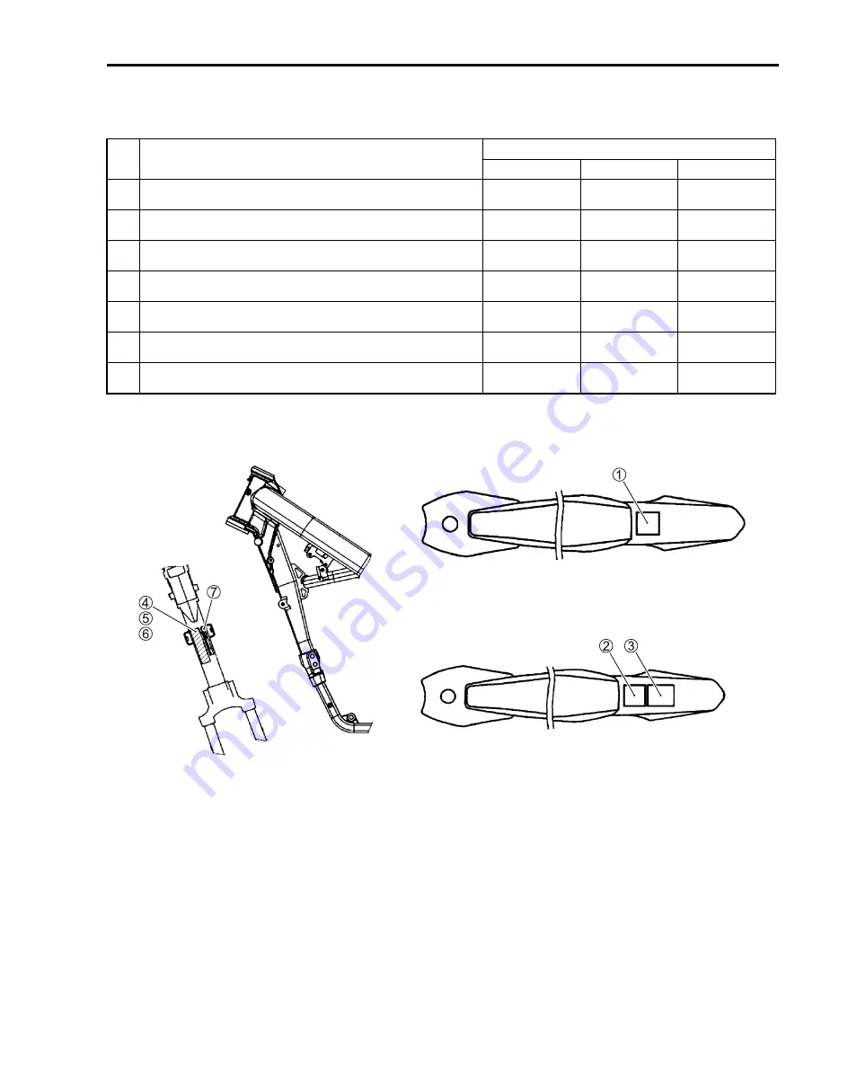
INFORMATION LABELS

E

: English

F

: French

A: Attached

No.

LABEL or PLATE NAME

APPLIED SPECIFICATION

E-03

E-19

E-28

1

General warning label 

E

A

2

General warning label 

E

A

A

3

General warning label 

F

A

A

4

EC approval mark label

A

5

ICES Canada label 

E

/

F

A

6

EPA plate 

E

A

7

Manufacture label 

E

A

A

A

For E-03

For E-19, 28

Summary of Contents for RM-Z250

Page 1: ......

Page 2: ...er sec tions as a guide for proper inspection and service This manual will help you know the motorcycle bet ter so that you can assure your customers of fast and reliable service This manual has been...

Page 3: ...E DONE Under the name of each system or unit is its exploded view Work instructions and other service information such as the tightening torque lubricating points and locking agent points are provided...

Page 4: ...Y PASTE in a ratio of 1 1 Use REAR SUSPENSION OIL SS 25 or equivalent Apply SUZUKI SUPER GREASE A or equivalent 99000 25010 Use engine coolant or equivalent Apply SUZUKI SILICONE GREASE or equivalent...

Page 5: ...ax Maximum Min Minimum R RH Right Hand S SAE Society of Automotive Engineers SDS Suzuki Diagnosis System T TO Sensor Tip Over Sensor TOS TP Sensor Throttle Position Sensor TPS WIRE COLOR B Black Lg Li...

Page 6: ...ostic Code Malfunction Code E Electronic Ignition El Engine Control Module ECM Engine Control Module ECM Fl Control Unit Engine Control Unit ECU Engine Coolant Level ECL Coolant Level Engine Coolant T...

Page 7: ...tion Diagnostic P Programmable Read Only Memory PROM R Random Access Memory RAM Read Only Memory ROM ROM T Throttle Body TB Throttle Body TB Throttle Body Fuel Injection TBI Throttle Body Fuel Injecti...

Page 8: ...RONT FORK OIL 1 5 REAR SUSPENSION OIL 1 5 ENGINE COOLANT 1 6 BREAK IN RUNNING IN 1 6 WHEN THE MOTORCYCLE IS NEW 1 6 WHEN ENGINE PARTS ARE REPLACED 1 6 INFORMATION LABELS 1 7 SPECIFICATIONS 1 8 DIMENSI...

Page 9: ...t use good judgement and basic mechanical safety principles If you are unsure about how to perform a particular service operation ask a more experienced mechanic for advice GENERAL PRECAUTIONS Proper...

Page 10: ...nd nuts tighten the larger sizes first Always tighten the bolts and nuts diagonally from the inside toward outside and to the speci fied tightening torque Whenever you remove oil seals gaskets packing...

Page 11: ...kets SERIAL NUMBER LOCATION The frame serial number or V I N Vehicle Identification Number 1 is stamped on the right side of the steering head pipe The engine serial number 2 is located on the rear si...

Page 12: ...re longer service life of your motorcy cle Use of SG SH SJ SL in API with JASO MA MA1 MA2 The recommended viscosity is SAE 10W 40 If an SAE 10W 40 motor oil is not available select an alternative acco...

Page 13: ...60 minutes using less than 1 2 throttle opening 3 Ride for 60 minutes using less than 3 4 throttle opening NOTE The break in running in period is the period of greatest wear The bolts and nuts of the...

Page 14: ...hed No LABEL or PLATE NAME APPLIED SPECIFICATION E 03 E 19 E 28 1 General warning label E A 2 General warning label E A A 3 General warning label F A A 4 EC approval mark label A 5 ICES Canada label E...

Page 15: ...0 mm 3 03 in Stroke 53 6 mm 2 11 in Displacement 249 cm3 15 2 cu in Compression ratio 13 5 1 Fuel system Fuel injection Air cleaner Polyurethane foam element Starter system Primary kick Lubrication sy...

Page 16: ...rake Front tire size 80 100 21 51M tube type Rear tire size 100 90 19 57M tube type ELECTRICAL Ignition type Electronic Ignition CDI Ignition timing 8 B T D C at 2 100 r min Spark plug NGK CR8EIA 10 C...

Page 17: ...NGINE OIL CHANGE 2 13 ENGINE OIL FILTER CHANGE 2 14 OIL STRAINERS 2 15 OIL STRAINER No 1 REMOVAL 2 15 OIL STRAINER No 2 REMOVAL 2 15 INSPECTION 2 16 OIL STRAINER No 2 INSTALLATION 2 17 OIL STRAINER No...

Page 18: ...N GUIDE BUFFER AND TENSIONER ROLLER 2 33 DRIVE CHAIN GUIDE INSPECTION 2 33 DRIVE CHAIN BUFFER AND ROLLER INSPECTION 2 33 BRAKES 2 34 BRAKE FLUID LEVEL 2 34 BRAKE PAD 2 35 FRONT BRAKE LEVER ADJUSTMENT...

Page 19: ...operation Throttle Play Smooth operation Crankcase breather hose Breather hose clogging and bend Engine idle speed Revolution speed Brake fluid Fluid level Brakes Brake lever position Brake pedal hei...

Page 20: ...tch disc plates wear and distortion Brake pads Wear Sprockets Wear Fuel tank Leakage Fuel hose Damage Hoses are connected Exhaust pipe and muffler Damage Cylinder head Combustion chamber carbon deposi...

Page 21: ...initial break in Cooling system I Replace radiator hose and engine coolant every year Flushing for overhaul or storage Clutch I Replace clutch plates as necessary Throttle cable and clutch cable I L...

Page 22: ...Every 12 hours Front fork oil R Change after 1st initial break in Front fork I Check front fork inner tube frequently for abnormality Check the air pressure Rear suspension I Check rear suspension sys...

Page 23: ...the spark plug condition electrode color carbon deposits spark plug gap and insulator damage If it is extremely worn or burnt replace the spark plug Also replace the spark plug if it has a broken ins...

Page 24: ...h fingers 09930 10121 Spark plug wrench set Spark plug 11 N m 1 1 kgf m 8 0 lbf ft Install the ignition coil plug cap securely Connect the lead wire coupler 4 NOTE The coupler 4 of ignition coil plug...

Page 25: ...e cleaning solvent A Immerse the element in the solvent and wash it A MOTUL AIR FILTER CLEAN or equivalent cleaning solvent Squeeze the element by grasping it to remove excess sol vent Do not twist or...

Page 26: ...ner body NOTE Follow the instructions below to prevent water from entering the engine through the air cleaner element when cleaning the motorcycle Cover the element with a plastic bag Install the seat...

Page 27: ...comes out from oil level check hole Tighten the oil check bolt 1 Engine oil check bolt 11 N m 1 1 kgf m 8 0 lbf ft Improper engine oil treatment is hazardous Read engine oil container instruction bef...

Page 28: ...be inspected may be affected Stop and leave the engine standstill for two minutes Thereaf ter if oil flows out when the engine oil check bolt 1 is removed the oil level is appropriate If oil is exces...

Page 29: ...Swing the motorcycle to the right and left two times and more Drain engine oil thoroughly Replace the gasket washers with new ones and tighten the drain plugs Engine oil drain plug 21 N m 2 1 kgf m 1...

Page 30: ...ilter 5 Apply engine oil lightly to the new O ring 6 Install the oil filter cap and tighten the bolts Oil filter cap bolt 11 N m 1 1 kgf m 8 0 lbf ft Add new engine oil and check the oil level as desc...

Page 31: ...rainer No 1 every engine oil change OIL STRAINER No 2 REMOVAL Drain engine oil 2 13 Remove the gearshift lever 9 3 Remove the magneto cover 15 17 Remove the oil pump No 2 cover 2 by removing its bolts...

Page 32: ...NSPECTION Check each oil strainer for any damage or clogging If the oil strainer is clogging clean the oil strainer with a com pressed air A OIl strainer No 1 B OIl strainer No 2 Clean the oil nozzle...

Page 33: ...s 4 to the specified torque Oil pump No 2 bolt 11 N m 1 1 kgf m 8 0 lbf ft Install the magneto cover 15 19 Install the gearshift lever 9 7 INSPECTION AFTER INSTALLATION Engine oil level and oil leakag...

Page 34: ...l dilute engine coolant and it may decrease cooling performance If the motorcycle is to be exposed to temperatures below 31 C 24 F the percentage of antifreeze should be increased to 55 or 60 accordin...

Page 35: ...ways COOLING SYSTEM INSPECTION Inspect the following items before practice and races Engine coolant leakage Radiator hose cracks and deterioration Radiator mounting condition Radiator over flow hose c...

Page 36: ...12 in when squeezing the lever until pressure is felt Tighten the lock nut 1 to the specified torque Clutch lever clearance A 2 3 mm 0 08 0 12 in Cable adjuster lock nut 2 2 N m 0 22 kgf m 1 60 lbf f...

Page 37: ...0 08 0 16 in Cable adjuster lock nut 2 2 N m 0 22 kgf m 1 60 lbf ft Inadequate throttle cable play can cause engine speed to rise suddenly when you turn the handle bars This can lead to loss of rider...

Page 38: ...C MAINTENANCE THROTTLE CABLE OIL SUPPLY Remove the throttle case 2 by removing its screws 1 Apply oil to the throttle cable Apply grease to the throttle cable spool 99000 25010 SUZUKI SUPER GREASE A o...

Page 39: ...er obtains 2 3 mm 0 08 0 12 in when squeezing the lever until pressure is felt Tighten the lock nut 1 Hot starter lever clearance A 2 3 mm 0 08 0 12 in Cable adjuster lock nut 2 2 N m 0 22 kgf m 1 60...

Page 40: ...edle pointed probe set 09900 26006 Engine tachometer Start the engine turn the starter knob idle screw 1 and set the engine idle speed as follows Engine idle speed 2 100 50 r min CRANKCASE BREATHER HO...

Page 41: ...ng NOTE The piston must be at top dead center TDC on the compres sion stroke in order to check or adjust the valve clearance The valve clearance should only be checked when the engine is cold Drain en...

Page 42: ...ze with micrometer to ensure its size Refer to the tappet shim selection table 2 27 28 for details NOTE Be sure to apply engine oil to tappet shim top and bottom faces When seating the tappet shim be...

Page 43: ...725 1 750 1 775 1 800 1 825 1 850 1 875 1 900 1 925 1 950 1 975 1 650 2 000 2 025 2 050 2 075 2 100 2 125 2 150 2 175 2 200 2 200 1 625 1 600 1 575 1 550 1 525 1 500 1 475 1 450 1 425 1 400 1 375 1 35...

Page 44: ...5 1 600 1 575 1 550 1 525 1 500 1 475 1 450 1 425 1 675 1 700 1 725 1 750 1 775 1 800 1 825 1 850 1 875 1 900 1 925 1 950 1 975 1 650 2 000 2 025 2 050 2 075 2 100 2 125 2 150 2 175 2 200 2 200 1 625...

Page 45: ...er head with a new one CYLINDER INSPECTION Remove the cylinder 6 7 Inspect the cylinder wall for any scratches nicks or other damage If any defects are found replace the cylinder with a new one PISTON...

Page 46: ...off the ground Inspect the drive chain slack at the middle point between the drive chain buffer and rear sprocket Drive chain slack A 35 45 mm 1 4 1 8 in CRANKCASE DRIVESHAFT OIL SEAL Remove the engin...

Page 47: ...t adjuster washers 4 are at the same position on scales 5 With the adjusters 3 held in position tighten the lock nuts 2 Push the adjuster washers 4 to the adjusters 3 and tighten the axle nut 1 Axle n...

Page 48: ...Suzuki Chain Lube or equivalent to the link plates and rollers Reassemble the drive chain NOTE Reassemble the drive chain clip so the slit end faces opposite the direction of rotation Inspect the dri...

Page 49: ...ace the defective parts with a new one DRIVE CHAIN BUFFER AND ROLLER INSPECTION Inspect the drive chain buffer 1 for wear and cracks Inspect the drive chain rollers 2 for wear If necessary replace the...

Page 50: ...l if it comes in contact with your skin or eyes Keep brake fluid away from children Call your doc tor immediately if brake fluid is swallowed and induce vomiting Flush eyes or skin with water if brake...

Page 51: ...n as follows Loosen the lock nut 1 Turn in or out adjuster 2 to obtain the proper brake lever position The standard adjuster length A is from 11 15 mm 0 4 0 6 in Tighten the lock nut 1 Adjuster length...

Page 52: ...l the air bleeder valve 1 Front fork air bleeder valve 1 3 N m 0 13 kgf m 1 0 lbf ft REAR SUSPENSION Move the rear suspension up and down several times and inspect for smooth movement Inspect for dama...

Page 53: ...bf ft Rear wheel rim lock 17 N m 1 7 kgf m 12 5 lbf ft TIRE PRESSURE Inspect front and rear tire pressure Tire pressure cold 70 110 kPa 0 7 1 1 kgf cm2 10 16 psi STEERING Inspect the steering by movin...

Page 54: ...the cable ends where they pivot 2 Throttle grip throttle housing cable A Pre race Lightly grease the inside of throttle spool Keep free from dirt 3 Rear brake pedal C Pre race Grease the brake pedal...

Page 55: ...wer 12 1 2 8 5 A Front brake caliper mounting bolt 26 2 6 19 0 B Front brake pad mounting pin 18 1 8 13 0 C Brake hose union bolt Front Rear 23 2 3 16 5 D Air bleeder valve Front Rear brake caliper 6...

Page 56: ...2 40 PERIODIC MAINTENANCE...

Page 57: ...NOTE Before testing the engine for compression pressure make sure that the cylinder head nuts are tightened to the specified torque values and the valves are properly adjusted Warm up the engine befor...

Page 58: ...ct the engine tachometer to the needle pointed probe 09900 25009 Needle pointed probe set 09900 26006 Engine tachometer Remove the exhaust pipe cover 2 by removing its bolts 1 Remove the oil gallery p...

Page 59: ...TROUBLESHOOTING TROUBLESHOOTING 3 1 3 CONTENTS ENGINE 3 2 RADIATOR COOLING SYSTEM 3 8 CHASSIS 3 9 BRAKES 3 10 ELECTRICAL 3 11...

Page 60: ...g connections Defective magneto No fuel reaching the intake manifold Clogged fuel filter or fuel hose Defective fuel pump Defective fuel pressure regulator Defective fuel injector Defective ECM Defect...

Page 61: ...fuel filter Defective fuel pump Defective fuel pressure regulator Defective ECT sensor Defective IAT sensor Fuel injector improperly operating Defective fuel injector Defective ECM Open or short circu...

Page 62: ...e from clutch Worn splines of countershaft or clutch sleeve hub Worn teeth of clutch plates Distorted clutch plates driven and drive Worn clutch release bearing Noise seems to come from crankshaft Rat...

Page 63: ...fuel hose resulting in inadequate fuel sup ply to injector Defective fuel pump Defective TP sensor Defective air flow system Clogged air cleaner element Defective throttle valve Sucking air from throt...

Page 64: ...t or replace Replace Clean or replace Retighten or replace Drain out excess oil Replace Replace Replace Replace Replace Replace Replace Replace Replace Engine overheats Defective engine internal parts...

Page 65: ...le play Replace Replace Replace Adjust Dragging clutch Some clutch spring weakened while others are not Distorted pressure plates or clutch plates Replace Replace Transmission will not shift Broken ge...

Page 66: ...ine coolant Radiator core clogged with dirt or scale Clogged water passage Air trapped in the cooling circuit Defective water pump Use incorrect coolant Defective ECM Defective ECT sensor Add coolant...

Page 67: ...place Adjust Front suspension too stiff Too viscous fork oil Too much fork oil Bent front fork Improperly set front fork damping force adjuster Replace Drain excess oil Replace Adjust Noisy front susp...

Page 68: ...logged return port of master cylinder Repair surface with sandpaper Correct pad fitting or replace Replace Replace Tighten to specified torque Replace brake fluid Disassemble and clean master cylinder...

Page 69: ...lace Spark plug elec trodes overheat or burn Too hot spark plug Overheated the engine Loose spark plug Too lean mixture Replace with cold type plug Tune up Retighten Inspect FI system Magneto does not...

Page 70: ...FORCE ADJUSTMENT 4 4 OIL QUANTITY MINOR ADJUSTMENT 4 5 OIL CHANGE Only for outer tube oil chamber 4 6 SPRING CHANGE 4 8 FRONT FORK TUNING PROCEDURE 4 10 REAR SUSPENSION TUNING 4 11 COMPRESSION DAMPING...

Page 71: ...d map either injection map for slightly leaner mixture or that for slightly richer mixture depending on the selected shunt wire NOTE The changeover is executed immediately after the engine has been st...

Page 72: ...isconnect the mode select coupler 2 from the bracket 1 Disconnect the mode select coupler cap 3 Connect the short wire 4 to the mode select coupler 2 Reinstall the mode select coupler Start the engine...

Page 73: ...o set the adjuster you must gently turn the adjuster screw clockwise until it stops then back it out the recommended num ber of turns Do not force the adjuster screw past the stopped position or you m...

Page 74: ...fork oil from the air bleed hole Front fork tuning procedure 4 10 99000 99001 SS5 SUZUKI FORK OIL SS 05 or equivalent Front fork air bleeder valve 1 3 N m 0 13 kgf m 1 0 lbf ft The fork oil quantity...

Page 75: ...e 18 6 09941 53630 Front fork top cap wrench Hold the front fork inverted position for more than 20 minutes to allow the fork oil to fully drain Force out the remaining oil using compressed air comple...

Page 76: ...dentification Slit mark on the spring end STD Oil quantity Oil quantity adjustable range Soft 51171 28H10 4 5 N mm 0 45 kgf mm 45 I 120 II See Fig 1 below 375 ml 12 68 13 20 US Imp oz 312 411 ml 10 55...

Page 77: ...nt fork inverted position for more than 20 minutes the allow the fork oil to fully drain 4 6 Force out the remaining oil using compressed air completely 4 6 Replace the spring The fork oil quantity mu...

Page 78: ...cified torque Lock nut center bolt 22 N m 2 2 kgf m 16 0 lbf ft Tighten the center bolt to the specified torque Center bolt 69 N m 6 9 kgf m 50 0 lbf ft b 1 mm 0 04 in and more Pour the specified amou...

Page 79: ...nd rebound damping force to a softer setting 2 Decrease fork oil capacity 3 Change the spring with an optional softer one Feels too soft overall and bottoms Jump Large bump When braking 1 Adjust the c...

Page 80: ...im lock tightness 2 37 COMPRESSION DAMPING FORCE ADJUSTMENT NOTE To set the adjuster you must gently turn the adjust screw or bolt clockwise until it stops then back it out the recommended num ber of...

Page 81: ...setting 14 clicks turn back SPRING PRE LOAD ADJUSTMENT Place a block under the chassis tube Remove the muffler and seat rail assembly 19 3 Loosen the lock nut 1 with the special tool 09910 60611 Unive...

Page 82: ...le normally in full riding gear Find the sag by subtracting L2 from L1 Standard sag range is 100 mm 3 94 in Spring Part No Spring rate Marking paint Set length adjustable range Soft 62211 37FK0 53 N m...

Page 83: ...the low speed compression damping force to a harder setting See note below 2 Adjust the rebound damping force to a harder setting See note below 3 Change the spring with an optional stiffer one 4 13...

Page 84: ...to bottom where as it felt fine before the front fork adjustment was made BALANCE TEST Stand next to the motorcycle on level ground Place one foot on the foot rest closest to you Sharply push down Th...

Page 85: ...ENGINE REMOVAL AND INSTALLATION 5 1 ENGINE REMOVAL AND INSTALLATION 5 CONTENTS ENGINE REMOVAL AND INSTALLATION 5 2 REMOVAL 5 2 INSTALLATION 5 6...

Page 86: ...move the fuel tank bolt 4 and rubber band 5 Lift and hold the fuel tank Disconnect the fuel pump coupler 6 Place a rag under the fuel hose 7 and disconnect the fuel hose 7 from the fuel pump Remove th...

Page 87: ...B by removing their nuts A Remove the exhaust pipe gasket C Remove the front protectors E by removing their bolts D Remove the radiator louvers F left and right Remove the radiator mounting bolts G le...

Page 88: ...p N Disconnect the magneto lead wire coupler O Remove the clamps P Remove the clutch cable bracket bolt Q and disconnect the clutch cable R NOTE Loosen the clutch cable adjuster when disconnecting Rem...

Page 89: ...n c Remove the snap ring d and engine sprocket e 09900 06107 Snap ring remover Open type Remove the engine mounting upper brackets g by removing their bolts and nut f Remove the engine mounting front...

Page 90: ...Tighten the engine mounting bolts nuts and swingarm pivot shaft nut to the specified torque NOTE After the engine has been installed and run make sure to retighten the fasteners as they are subject to...

Page 91: ...nd engine sprocket cover 4 Tighten the engine sprocket cover bolts 5 to the specified torque Engine sprocket cover bolt 11 N m 1 1 kgf m 8 0 lbf ft Install the gearshift lever 6 in the correct positio...

Page 92: ...e pedal pivot bolt 29 N m 2 9 kgf m 21 0 lbf ft Install the clip A washer B and cotter pin C Install the kick starter lever D in the correct position 8 7 8 Tighten the kick starter lever bolt E to the...

Page 93: ...cable I with the matching mark H on the clutch cable bracket Tighten the clutch cable bracket bolt J to the specified torque Clutch cable bracket bolt 6 N m 0 6 kgf m 4 5 lbf ft Install the muffler j...

Page 94: ...ween exhausted pipe and radiator hose Be sure to tighten the bolts and nuts in the following order 1 Muffler mounting front bolt N and rear bolt O 2 Exhaust pipe nuts 3 Connector clamp bolt P Exhaust...

Page 95: ...CAMSHAFT INSPECTION 6 9 CAM CHAIN TENSION ADJUSTER INSPECTION 6 11 CAM CHAIN No 1 GUIDE CAM CHAIN No 2 GUIDE AND CAM CHAIN TENSIONER INSPECTION 6 11 CYLINDER HEAD AND VALVE INSPECTION 6 12 INTAKE PIP...

Page 96: ...head B Camshaft journal holder bolt A Initial 25 2 5 18 0 4 Cylinder head gasket C Spark plug A Final 51 5 1 37 0 5 C ring D Oil gallery plug BDE 10 1 0 7 0 6 Cylinder head cover E Cylinder head base...

Page 97: ...TEM N m kgf m lbf ft 3 Tappet B Cam chain tensioner A 23 2 3 16 5 4 Valve spring C Cam chain tension adjuster BCD 10 1 0 7 0 5 Exhaust valve A Cam chain tension adjuster cap bolt 6 Intake valve B Cam...

Page 98: ...k 13 2 3 Remove the ignition coil plug cap and spark plug 2 7 Remove the cylinder head cover 2 and gasket 3 by remov ing their bolts 1 Remove the cylinder head cover No 2 gasket 4 CAMSHAFTS AUTOMATIC...

Page 99: ...fts are aligned with the mating surface of the cylinder head C Timing mark Disconnect the condenser coupler 3 and remove the con denser 4 Remove the cam chain tension adjuster cap bolt 5 gasket 6 bar...

Page 100: ...uffler connector clamp bolt 1 Remove the exhaust pipe 3 by removing their nuts 2 Remove the exhaust pipe gasket 4 Disconnect the radiator hoses 6 by loosing their clamp screws 5 Disconnect the ECT sen...

Page 101: ...does not come off easily lightly tap it using a plastic hammer Remove the cylinder head gasket G dowel pins H and cam chain No 1 guide I CYLINDER REMOVAL Remove the cylinder head 6 6 Remove the cylin...

Page 102: ...y spread the ring opening with your thumbs and then push up the opposite side of the ring 4 to remove it Remove the oil ring in the same procedure CAM CHAIN CAM CHAIN TENSIONER AND CAM CHAIN No 1 GUID...

Page 103: ...lace the camshaft assembly CAMSHAFT INSPECTION CAM SPROCKET Inspect the sprocket teeth for wear If they are worn replace the camshafts crankshaft and cam chain as a set CAMSHAFT BEARING Inspect the be...

Page 104: ...e the plastigauge to read the clearance at the widest por tion which is specified as follows 09900 22301 Plastigauge 0 025 0 076 mm 09900 22302 Plastigauge 0 051 0 152 mm Tighten the camshaft journal...

Page 105: ...Small bore gauge 18 35 mm Camshaft journal O D Standard IN EX 21 959 21 980 mm 0 8645 0 8654 in 09900 20205 Micrometer 0 25 mm CAM CHAIN TENSION ADJUSTER INSPECTION Remove the cam chain tension adjus...

Page 106: ...09919 28620 Sleeve protector Exhaust side Install the sleeve protector b between the valve spring and cylinder head Using the special tools compress the valve spring and remove the two cotter halves...

Page 107: ...reading at several places indicated If the largest reading at any position of the straightedge exceeds the limit replace the cylinder head Cylinder head distortion Service Limit 0 05 mm 0 002 in 0990...

Page 108: ...h valve stem and valve face for wear and pitting If it is worn or damaged replace the valve with a new one VALVE STEM DEFLECTION Lift the valve about 10 mm 0 39 in from the valve seat Measure the valv...

Page 109: ...emoved for replacement after inspecting related parts carry out the steps shown in valve guide servicing VALVE GUIDE SERVICING Drive the valve guide out toward the intake or exhaust cam shaft side wit...

Page 110: ...6 33210 Valve guide reamer 4 5 mm 09916 34542 Reamer handle NOTE Be sure to cool down the cylinder head to ambient air temper ature Insert the reamer from the combustion chamber and always turn the re...

Page 111: ...ed 2 25 INTAKE EXHAUST Seat angle 15 45 60 Seat width 0 9 1 1 mm 0 035 0 043 in Valve diameter 31 mm 1 22 in 25 mm 0 98 in Valve guide I D 4 500 4 512 mm 0 1772 0 1776 in 60 45 15 The valve seat conta...

Page 112: ...replace the spring Valve spring free length Service limit IN 37 1 mm 1 46 in EX 37 5 mm 1 48 in 09900 20101 Vernier calipers 150 mm Valve spring tension Standard IN 142 157 N 14 5 16 0 kgf 33 55 mm 31...

Page 113: ...otector For IN side 09916 14530 Valve lifter attachment For EX side 09919 28610 Sleeve protector For EX side 09916 84511 Tweezer Be sure that the rounded lip E of the cotter fits snugly into the groov...

Page 114: ...emoving its bolts 2 INTAKE PIPE INSTALLATION Apply grease to O ring of the intake pipe 99000 25010 SUZUKI SUPER GREASE A or equivalent Install the intake pipe 1 and tighten the intake pipe bolts 2 to...

Page 115: ...at any position of the straightedge exceeds the limit replace the cylinder Cylinder distortion Service Limit 0 05 mm 0 002 in 09900 20803 Thickness gauge CYLINDER BORE Inspect the cylinder wall for a...

Page 116: ...the piston to cylinder clearance exceeds the service limit replace the cylinder or the piston or both Piston to cylinder clearance Service Limit 0 120 mm 0 0047 in PISTON PIN AND PIN BORE Measure the...

Page 117: ...andard 1st 1 01 1 03 mm 0 0398 0 0406 in Oil 1 51 1 53 mm 0 0594 0 0602 in Piston ring thickness Standard 1st 0 97 0 99 mm 0 0382 0 0390 in PISTON RING FREE END GAP AND PISTON RING END GAP Measure the...

Page 118: ...conrod Conrod small end I D Service Limit 16 040 mm 0 6315 in 09900 20602 Dial gauge 09900 22403 Small bore gauge 18 35 mm CONROD BIG END SIDE CLEARANCE Inspect the conrod side clearance by using a t...

Page 119: ...bolt 10 N m 1 0 kgf m 7 0 lbf ft Install the cam chain 4 to the crankshaft sprocket Install the cam chain guide retainer 5 and tighten the cam chain guide retainer bolt 6 to the specified torque Cam c...

Page 120: ...After placing the spacer fit the two side rails 2 NOTE Side designations top and bottom are not applied to the spacer and side rails you can position each either way A INCORRECT B CORRECT Install the...

Page 121: ...ly MOLYBDENUM OIL SOLUTION onto its surface MOLYBDENUM OIL SOLUTION Place a clean rag over the cylinder base to prevent the piston pin circlip 3 from dropping into crankcase Install the piston pin cir...

Page 122: ...LUTION to the sliding surface of the piston and cylinder bore MOLYBDENUM OIL SOLUTION Hold each piston ring with the piston ring sections positioned correctly and put it into the cylinder Make sure th...

Page 123: ...lts 5 to the specified torque Cylinder head bolt Initial 25 N m 2 5 kgf m 18 0 lbf ft Final 51 N m 5 1 kgf m 37 0 lbf ft After tightening the cylinder head bolts to specification tighten the cylinder...

Page 124: ...rk A with the center of the groove B of the timing inspection hole Just before installing the camshaft into the cylinder head apply MOLYBDENUM OIL SOLUTION to the camshaft jour nals camshaft journal h...

Page 125: ...e exhaust camshaft side going towards the intake camshaft side Engage the 13th roller pin on the cam chain with the timing marked E on the camshaft sprocket intake side Refer to the following illustra...

Page 126: ...en the camshaft journal holder bolts in ascending order of numbers to the specified torque Camshaft journal holder bolt 10 N m 1 0 kgf m 7 0 lbf ft CAM CHAIN TENSION ADJUSTER Retract the push rod by p...

Page 127: ...hafts 6 31 Inspect the valve clearance 2 25 Apply grease to the O rings 9 99000 25010 SUZUKI SUPER GREASE A or equivalent Tighten the TDC plug 0 and crankshaft hole plug A to the specified torque TDC...

Page 128: ...oil to both sides of gaskets 5 Tighten the cylinder head cover bolts 6 to the specified torque Cylinder head cover bolt 14 N m 1 4 kgf m 10 0 lbf ft Install the spark plug and ignition coil plug cap...

Page 129: ...7 2 CLUTCH 7 2 CLUTCH PLATE 7 3 REMOVAL 7 3 INSPECTION 7 5 INSTALLATION 7 6 PRIMARY DRIVEN GEAR AND CLUTCH SLEEVE HUB 7 8 REMOVAL 7 8 INSPECTION 7 9 INSTALLATION 7 9 CLUTCH RELEASE CAMSHAFT 7 11 REMOV...

Page 130: ...EM N m kgf m lbf ft 3 Push piece B Needle bearing A 10 1 0 7 0 4 Clutch driven No 1 plate Silver C Primary driven gear B 90 9 0 65 0 5 Clutch driven No 1 plate Gray D Spacer 6 Spring washer E Washer 7...

Page 131: ...s gasket 2 Remove the clutch spring set bolts 3 and clutch springs NOTE Loosen the clutch spring set bolts 3 little by little and diagonally Remove the clutch pressure plate 4 washer 5 bearing 6 and p...

Page 132: ...ch drive plates 9 and driven plates 0 NOTE Mark the paint mark a to the clutch driven No 2 plate A Clutch driven No 2 plate B Clutch driven No 1 plate C Direction of outside Remove the spring washer A...

Page 133: ...ve plate claw width Service Limit 13 05 mm 0 514 in 09900 20101 Vernier calipers DRIVEN PLATE Measure the driven plate distortion Driven plate distortion Service Limit 0 10 mm 0 004 in 09900 20803 Thi...

Page 134: ...earing If any defects are found replace the clutch release bearing with a new one INSTALLATION Install the clutch plates in the reverse order of removal Pay attention to the following points Install t...

Page 135: ...orque NOTE Tighten the clutch spring set bolts 9 diagonally Clutch spring set bolt 10 N m 1 0 kgf m 7 0 lbf ft Install the gasket 0 and clutch cover A Tighten the clutch cover bolts A B diagonally to...

Page 136: ...s 7 3 4 Flatten the lock washer 1 Hold the clutch sleeve hub 3 with the special tool and loosen the clutch sleeve hub nut 2 09920 53740 Clutch sleeve hub holder 09920 31020 Extension handle Remove the...

Page 137: ...ound replace the bearing or spacer with a new one INSTALLATION Install the primary driven gear and clutch sleeve hub in the reverse order of removal Pay attention to the following points Apply engine...

Page 138: ...ock washer to secure the nut Reassemble the clutch plates and pressure plate 7 6 7 Install the gasket 8 and clutch cover 9 Tighten the clutch cover bolts A B diagonally to the speci fied torque Clutch...

Page 139: ...tch release camshaft 4 out of crankcase INSPECTION CLUTCH RELEASE CAMSHAFT Inspect the clutch release camshaft for abnormal deflection and damage If any defects are found replace the release camshaft...

Page 140: ...valent Apply grease to the oil seal lip 99000 25010 SUZUKI SUPER GREASE A or equivalent Install the clutch release camshaft 1 and connect the clutch cable 2 Install the push rod and pressure plate 7 7...

Page 141: ...KICK STARTER KICK STARTER 8 1 8 CONTENTS CONSTRUCTION 8 2 KICK STARTER 8 2 KICK STARTER 8 3 REMOVAL 8 3 INSPECTION 8 4 INSTALLATION 8 5...

Page 142: ...ring guide 0 Spring ITEM N m kgf m lbf ft 3 Spring A Wave washer AC 10 1 0 7 0 4 Kick starter guide B Kick starter idle gear B 29 2 9 21 0 5 Washer A Kick starter lever screw 6 Kick starter drive gear...

Page 143: ...ake pedal 17 20 Disconnect the radiator hose 2 by loosing its clamp screw 1 Remove the kick starter lever 4 by removing its bolt 3 Remove the right crankcase cover 5 by removing its bolts Remove the d...

Page 144: ...ar F 09900 06107 Snap ring remover Open type Remove the kick starter guide L by removing its bolt K INSPECTION Inspect the oil seal lip A for wear and damage If any defects are found replace the oil s...

Page 145: ...on to the following points Install the kick starter guide 1 and tighten the kick starter guide bolt 2 to the specified torque Kick starter guide bolt 10 N m 1 0 kgf m 7 0 lbf ft Install the washer 3 o...

Page 146: ...rter 0 align the wide spline teeth C and D Install the spring A to the kick starter shaft Apply MOLYBDENUM OIL SOLUTION to the stopper portion E of the kick starter and F of the stopper guide MOLYBDEN...

Page 147: ...all the right crankcase cover F Tighten the right crankcase cover bolts a b c d to the specified torque Right crankcase cover bolt 11 N m 1 1kgf m 8 0 lbf ft a Length 30 mm 1 2 in b Length 60 mm 2 4 i...

Page 148: ...que Kick starter lever bolt 29 N m 2 9 kgf m 21 0 lbf ft Install the brake pedal 17 20 Connect the radiator hose 20 24 INSPECTION AFTER INSTALLATION Engine oil level and oil leakage 2 12 Engine coolan...

Page 149: ...ING GEARSHIFTING 9 1 9 CONTENTS CONSTRUCTION 9 2 GEARSHIFT LINKAGE 9 2 GEARSHIFT LINKAGE 9 3 REMOVAL 9 3 INSPECTION 9 5 INSTALLATION 9 5 GEAR POSITION GP SWITCH 9 8 REMOVAL 9 8 INSPECTION 9 8 INSTALLA...

Page 150: ...tch A 23 2 3 16 5 4 Gearshift pawl lifter A Gearshift arm stopper B 8 5 0 85 6 0 5 Gearshift roller B Pawl lifter screw C 24 2 4 17 5 6 Gearshift cam driven gear C Gearshift cam driven gear pin D 10 1...

Page 151: ...llation Remove the right crankcase cover and clutch component parts 7 9 8 3 Remove the gearshift shaft assembly 3 and washer 4 Remove the washer 4 snap ring 6 and return spring 7 from the gearshift sh...

Page 152: ...nd gear shift roller D from the gearshift cam driven gear 0 Remove the gearshift cam driven gear pin E and gearshift cam stopper plate F Remove the gearshift cam stopper H spring I and washer J by rem...

Page 153: ...LLATION Install the gearshift in the reverse order of removal Pay atten tion to the following points Install the washer 1 and gearshift arm stopper 2 Apply a small quantity of THREAD LOCK SUPER to the...

Page 154: ...r pin 8 and tighten it to the specified torque 99000 32050 THREAD LOCK 1342 or equivalent Gearshift cam driven gear pin 24 N m 2 4 kgf m 17 5 lbf ft Fit the springs 9 pins 0 pawls A and gearshift roll...

Page 155: ...e stopper D of gearshift arm between the return spring ends E 09900 06107 Snap ring remover Open type Install the gearshift shaft assembly J NOTE Pinch the gearshift arm stopper F with return spring e...

Page 156: ...plate 4 Remove the clamps 5 Remove the GP switch 7 by removing its bolts 6 Remove the O ring 8 switch contacts 9 and springs 0 INSPECTION Refer to page 12 52 53 for details INSTALLATION Install the g...

Page 157: ...que GP switch mounting bolt 6 5 N m 0 65 kgf m 4 7 lbf ft Install the front chain guide plate 6 and engine sprocket cover 7 Tighten the engine sprocket cover bolts 8 to specified torque Engine sprocke...

Page 158: ...EED VALVE REMOVAL 10 6 TRANSMISSION INSPECTION 10 7 CONROD INSPECTION 10 8 CRANKSHAFT INSPCECTION 10 8 OIL REED VALVE INSPECTION 10 8 CRANKCASE REED VALVE INSPECTION 10 9 OIL SEAL INSPECTION 10 9 OIL...

Page 159: ...riven gear A Gearshift fork No 3 ITEM N m kgf m lbf ft 3 4th driven gear B Gearshift cam A 8 5 0 85 6 0 4 3rd driven gear C Countershaft 5 Driveshaft D 5th drive gear 6 Sliding dog E 3rd 4th drive gea...

Page 160: ...AND CRANKSHAFT 10 3 CRANKSHAFT 1 Right crankshaft 5 Primary drive gear 2 Conrod A Bearing retainer screw ITEM N m kgf m lbf ft 3 Crank pin B Primary drive gear nut A 8 5 0 85 6 0 4 Left crankshaft B...

Page 161: ...ensioner 6 8 Remove the right crankcase cover 8 3 PRIMARY DRIVE GEAR REMOVAL Hold the crankshaft immovable with the special tool 09914 61010 Gear holder Remove the primary drive gear nut 1 and washer...

Page 162: ...crankcase bolts 4 Separate the crankcase with the special tool 09920 13120 Crankshaft remover NOTE Set the crankcase separating tool to the clutch side of the crankcase Separate the crankcase graduall...

Page 163: ...move the countershaft assembly 7 and driveshaft assem bly 8 CRANKSHAFT REMOVAL Remove the crankshaft with the special tool 09920 13120 Crankshaft remover CRANKCASE REED VALVE REMOVAL Remove the reed v...

Page 164: ...ace the gearshift cam with a new one Inspect the gearshift forks and shaft for wear and damage If any defects are found replace the gearshift fork or shaft Measure the gearshift fork to groove clearan...

Page 165: ...3 0 mm 0 12 in 09900 20607 Dial gauge 09900 20701 Dial gauge chuck 09900 21304 V blocks CRANKSHAFT INSPCECTION Measure the crankshaft runout with V blocks and dial gauge NOTE Place the crankshaft ont...

Page 166: ...rankcase reed valve and reed valve guide with a new one OIL SEAL INSPECTION Inspect each oil seal lip A for wear and damage If any defects are found replace the oil seal with a new one OIL SEAL REMOVA...

Page 167: ...22 Attachment Oil seal 3 17 Attachment Apply grease to each oil seal lip 99000 25010 SUZUKI SUPER GREASE A or equivalent NOTE Be sure to check the direction of the crankshaft bearing oil seal 5 befor...

Page 168: ...2 Remove the bearings 3 4 5 6 7 8 with the special tool Bearing 3 7 37 Attachment Bearing 4 8 40 Attachment Bearing 5 42 Attachment Bearing 6 32 Attachment 09913 70210 Bearing installer set 10 75 Rem...

Page 169: ...new bearings with the special tool 09913 70210 Bearing installer set Bearing 1 52 Attachment Bearing 2 8 40 Attachment Bearing 3 6 62 Attachment Bearing 4 32 Attachment Bearing 5 47 Attachment Bearin...

Page 170: ...ecified torque Bearing retainer screw 8 5 N m 0 85 kgf m 6 0 lbf ft CRANKCASE REED VALVE INSTALLATION Install the crankcase reed valve 1 and reed valve guide 2 direction as shown Tighten the reed valv...

Page 171: ...9000 25010 SUZUKI SUPER GREASE A or equivalent Install a new oil seal 4 with the special tool 09930 35010 Rotor remover NOTE Be sure to check the direction of the crankshaft bearing oil seal 4 before...

Page 172: ...ISSION AND CRANKSHAFT 10 15 TRANSMISSION INSTALLATION NOTE Install the snap ring 1 in the groove and locate its end as shown in the illustration a Thrust b Sharp edge Replace the snap ring 1 with a ne...

Page 173: ...n both ends of the driveshaft positively Install the washer C located in end of the countershaft 3 pos itively Install the gearshift forks 4 5 6 as shown 4 For 5th driven gear 5 For sliding dog 6 For...

Page 174: ...bolts separate the crankcase and con firm that the transmission parts are assembled correctly Install the oil strainer No 1 and oil strainer cap 3 2 17 a Length 40 mm 1 6 in b Length 50 mm 2 0 in c Le...

Page 175: ...the clutch component parts 7 9 10 Apply THREAD LOCK SUPER to the primary drive gear nut 3 99000 32110 THREAD LOCK SUPER 1322 or equivalent Hold the magneto rotor with the special tool and tighten the...

Page 176: ...GE 11 3 OIL PRESSURE CHECK 11 3 OIL STRAINER REMOVAL 11 3 OIL STRAINERS INSPECTION 11 3 OIL STRAINER INSTALLATION 11 3 OIL REED VALVE REMOVAL 11 3 OIL REED VALVE INSPECTION 11 3 OIL REED VALVE INSTALL...

Page 177: ...11 2 LUBRICATION SYSTEM ENGINE LUBRICATION SYSTEM ENGINE LUBRICATION SYSTEM CHART CAM CHAIN...

Page 178: ...ION 2 16 OIL STRAINER INSTALLATION OIL STRAINER No 1 2 17 OIL STRAINER No 2 2 17 OIL REED VALVE REMOVAL 10 5 OIL REED VALVE INSPECTION Inspect the oil reed valve for wear and damage If any defects are...

Page 179: ...ng 09913 70210 Bearing installer set 10 75 Oil seal 22 Attachment 09900 06108 Snap ring remover Close type Apply grease to the oil seal lip 99000 25010 SUZUKI SUPER GREASE A or equivalent OIL PUMP No...

Page 180: ...oving its bolts 7 Remove the following parts from the oil pump No 1 Outer rotor 9 Inner rotor 0 Pin A Washer B Oil pump No 1 cover C Oil pump driven gear shaft D OIL PUMP No 2 Drain engine oil 2 13 Re...

Page 181: ...r any defects or wear If necessary replace the defective parts with a new one OIL PUMP No 1 AND No 2 INSTALLATION OIL PUMP No 1 Install the oil pump No 1 in the reverse order of removal Pay attention...

Page 182: ...00 32110 THREAD LOCK SUPER 1322 or equivalent Hold the crankshaft immovable with the special tool and tighten the primary drive gear nut B to the specified torque 09914 61010 Gear holder Primary drive...

Page 183: ...bolts 6 to the specified torque Oil strainer No 2 bolt 5 5 N m 0 55 kgf m 4 0 lbf ft Install the oil pump No 2 cover 7 and tighten the oil pump No 2 bolts 8 to the specified torque Oil pump No 2 bolt...

Page 184: ...CTION 12 19 SELF DIAGNOSTIC PROCEDURES 12 19 SELF DIAGNOSIS RESET PROCEDURE 12 20 USE OF SDS DIAGNOSTIC PROCEDURES 12 20 USE OF SDS DIAGNOSIS RESET PROCEDURE 12 21 SHOW DATA WHEN TROUBLE DISPLAING DAT...

Page 185: ...SHAFT ROTATION SIGNAL SENSOR REMOVAL AND INSTALLATION 12 61 IAP SENSOR INSPECTION 12 61 IAP SENSOR REMOVAL AND INSTALLATION 12 61 TP SENSOR INSPECTION 12 61 TP SENSOR REMOVAL AND INSTALLATION 12 61 EC...

Page 186: ...y and do not pull the lead wires Inspect each terminal on the connector coupler for looseness or bending Push in the coupler straightly An angled or skewed insertion may cause the terminal to be defor...

Page 187: ...l to open Connect the probe as shown to avoid opening of female ter minal Never push in the probe where male terminal is supposed to fit Check the male connector for bend and female connector for exce...

Page 188: ...00 Battery connection in reverse polarity is strictly prohibited Such a wrong connection will damage the components of the FI system instantly when reverse power is applied Removing the condenser coup...

Page 189: ...result ELECTRICAL CIRCUIT INSPECTION PROCEDURE While there are various methods for electrical circuit inspection described here is a general method to check for open and short circuit using an ohmmete...

Page 190: ...and removing 2 Check each terminal for bend and proper alignment Using continuity inspect or voltage check procedure as described below inspect the wire harness terminals for open circuit and poor co...

Page 191: ...ues are as listed below a resistance abnormality exists which causes the voltage drop in the circuit between terminals A and B Voltage Between C and body ground Approx 5 V B and body ground Approx 5 V...

Page 192: ...e ments using the highest range When measuring the resistance with the multi circuit tester 1 will be shown as 10 00 M and 1 flashes in the display Check that no voltage is applied before making the m...

Page 193: ...d various compensations These compensations are determined according to the signals from various sensors that detect the engine and driving conditions Intake Air Pressure Sensor IAP Sensor Intake air...

Page 194: ...me it monitors the voltage signal for compensation of the fuel injection time volume A longer injection time is needed to adjust injection volume in the case of low voltage ACCELERATION SIGNAL DECELER...

Page 195: ...12 12 FI SYSTEM DIAGNOSIS FI SYSTEM PARTS LOCATION A ECM D Fuel pump B Ignition coil plug cap E ECT sensor C TO sensor F Fuel injector...

Page 196: ...FI SYSTEM DIAGNOSIS 12 13 A ECM J CKP sensor G IAP Sensor K Crankshaft rotation signal sensor H IAT Sensor L GP switch I TP Sensor...

Page 197: ...ke air temperature sensor IATS Engine coolant temperature sensor ECTS Engine stop switch Gear position switch Ignition coil plug cap Fuel injector FI indicator light option Fuel pump Regulator rectifi...

Page 198: ...or signal TPS M 6 IAP sensor signal IAPS N Sensor ground E2 7 O IAT sensor signal IATS 8 Ground E1 P 9 CKP sensor signal CKPS Q 0 Serial data for self diagnosis R A Blank S Map select input MAP 2 B Ne...

Page 199: ...g the battery lead wire 2 The DTC is displayed by flashing pattern of FI indicator light This means that the ECM has not received signals indicating a correct condition from the sensors or device con...

Page 200: ...ator 14 TP sensor 12 31 15 ECT sensor 12 35 17 IAP sensor 12 39 21 IAT sensor 12 44 23 TO sensor 12 48 24 Ignition signal 12 51 Ignition coil plug cap 31 Gear position signal 12 52 GP switch 32 Fuel...

Page 201: ...rovided with fail safe function to allow the engine to start and the motorcycle to run in a mini mum performance necessary even under malfunction condition The engine can start and can run even if the...

Page 202: ...king the DTC Diagnostic Trouble Code Such discon nection will erase the DTC DTC can be checked by the FI indicator light assy Before checking DTC read SELF DIAGNOSIS FUNCTION 12 16 carefully to have g...

Page 203: ...e coupler 12 19 36890 28H00 Battery lead wire option NOTE The DTC Diagnostic Trouble Code check does not require the battery to be connected during running of the engine but it needs the battery power...

Page 204: ...red in the ECM Therefore erase the history code memorized in the ECM using SDS tool NOTE The malfunction code is memorized in the ECM also when the wire coupler of any sensor is disconnected Therefore...

Page 205: ...or stopped when a malfunction was detected by checking the show data when trouble This show data when trouble function can record the maximum of two Diagnostic Trouble Codes in the ECM Also ECM has a...

Page 206: ...to be determined Also in the case of a customer vehicle which is not periodically brought in for service with no past data value having been saved if the data value of a good vehicle condition have be...

Page 207: ...GNOSIS Data at 3 000 r min under no load Data at the time of racing Approx 3 000 r min Check the manifold absolute pressure XX kPa Check the engine coolant temperature XX C Throttle Quick wide open Th...

Page 208: ...egative pressure during idling 90 C Data of manifold absolute pressure operation at the time of starting Check the manifold absolute pressure XX kPa Check the engine coolant temperature Approx 90 C Ch...

Page 209: ...a to the past data that have been saved under the same condition then you may determine how changes have occurred with the pass of time and identify what problem is currently occurring With DTC not ou...

Page 210: ...nge 15 P0115 is indicated ECT sensor lead wire coupler connection P0115 H Sensor voltage is higher than specified value ECT sensor circuit open or ground circuit open L Sensor voltage is lower than sp...

Page 211: ...om the battery P0351 31 Gear posi tion signal Gear position signal voltage should be higher than the following Gear position switch voltage 0 89 V If lower than the above value for 3 sec onds or more...

Page 212: ...nce CKP sensor resistance 80 120 Green Red DETECTED CONDITION POSSIBLE CAUSE The signal does not reach ECM for 1 second or more after receiving the IAP sensor input signal Metal particles or foreign m...

Page 213: ...olt adaptor 09900 25008 Multi circuit tester set Tester knob indication Voltage Is the voltage OK YES Go to step 2 NO Replace the CKP sensor with a new one YES G W or BI wire open or shorted to ground...

Page 214: ...in the following range Difference between actual throttle open ing and opening calculated by ECM is larger than specified value 0 39 V Sensor voltage 4 51 V TP sensor maladjusted TP sensor circuit ope...

Page 215: ...ep 1 When indicating P0120 H 1 Stop the engine 2 Check the TP sensor coupler 1 for loose or poor contacts If OK then check the TP sensor lead wire continuity 3 Disconnect the TP sensor coupler 4 Remov...

Page 216: ...the continuity OK Step 1 When indicating P0120 L 1 Stop the engine 2 Check the TP sensor coupler 1 for loose or poor contacts If OK then check the TP sensor lead wire continuity 3 Disconnect the TP s...

Page 217: ...ween Yellow and B Br by turning the throttle grip TP sensor output voltage Throttle valve is closed Approx 0 6 V Throttle valve is opened Approx 3 8 V 09900 25008 Multi circuit tester set 09900 25009...

Page 218: ...wire to the service coupler 12 19 DETECTED CONDITION POSSIBLE CAUSE 15 Output voltage is not within the following range 0 2 V Sensor voltage 4 9 V ECT sensor circuit open or short ECT sensor malfunct...

Page 219: ...1 for loose or poor contacts If OK then check the ECT sensor lead wire continuity 3 Remove the fuel tank 13 2 3 4 Disconnect the ECT sensor coupler and ECM coupler 5 Insert the needle pointed probes t...

Page 220: ...uit condition is OK Tester knob indication Continuity test 7 Connect the ECT sensor coupler 1 and ECM coupler 8 Insert the needle pointed probe to the lead wire coupler 9 Connect a 12 volts battery by...

Page 221: ...ECT sensor specification YES B Bl or B Br wire open or shorted to ground or poor L or N connection If wire and connection are OK intermittent trou ble or faulty ECM Recheck each terminal and wire har...

Page 222: ...ns as well as altitude Take that into consideration when inspecting voltage Clogged vacuum passage between throttle body and IAP sensor Air being drawn from vacuum passage between throttle body and IA...

Page 223: ...obe set 36890 28H00 Battery lead wire option Tester knob indication Voltage Is the voltage OK Step 1 When indicating P0105 H 1 Stop the engine 2 Check the IAP sensor coupler 1 for loose or poor contac...

Page 224: ...ester knob indication Continuity test Is the continuity OK Step 1 When indicating P0105 L 1 Stop the engine 2 Check the IAP sensor coupler 1 for loose or poor contacts If OK then check the IAP sensor...

Page 225: ...he IAP sensor out put voltage 2 Connect the ECM coupler and IAP sensor coupler 3 Insert the needle pointed probes to the lead wire coupler 4 Kickstart the engine at idle speed 5 Measure the IAP sensor...

Page 226: ...uge 09900 25008 Multi circuit tester set Tester knob indication Voltage Is the voltage OK Output voltage VCC voltage 4 5 5 0 V ambient temp 25 C 77 F YES G B R Bl or B Br wire open or shorted to groun...

Page 227: ...y by using the battery lead wire to the service coupler 12 19 DETECTED CONDITION POSSIBLE CAUSE 21 Output voltage is not within the following range 0 19 V Sensor voltage 4 93 V IAT sensor circuit open...

Page 228: ...ts If OK then check the IAT sensor lead wire continuity 4 Remove the fuel tank 13 2 3 5 Disconnect the IAT sensor coupler and ECM coupler 12 60 6 Insert the needle pointed probes to the lead wire coup...

Page 229: ...e tester the circuit condition is OK Tester knob indication Continuity test 7 Connect the IAT sensor coupler 8 Insert the needle pointed probe to the lead wire coupler 9 Connect a 12 volts battery by...

Page 230: ...ce measurement method is the same way as that of the ECT sensor 12 62 2 YES Dg or B Br wire open or shorted to ground or poor O or N connection If wire and connection are OK intermittent trou ble or f...

Page 231: ...should be the follow ing for 1 second and more 0 17 V Sensor voltage 4 73 V TO sensor circuit open or short TO sensor malfunction ECM malfunction P1651 H Sensor voltage is higher than specified value...

Page 232: ...nsor coupler and ECM coupler 5 Check the continuity between R Bl wire A and Br W wire C If the sound is not heard from the tester the circuit condition is OK 6 Insert the needle pointed probes to the...

Page 233: ...wire C and B Br wire B If the sound is not heard from the tester the circuit condition is OK 7 Insert the needle pointed probes to the lead wire coupler 8 Check the continuity between R Bl wire A and...

Page 234: ...circuit tester set 09900 25009 Needle pointed probe set 36890 28H00 Battery lead wire option Tester knob indication Voltage Is the voltage OK 24 P0351 IGNITION SYSTEM CIRCUIT MALFUNCTION Refer to the...

Page 235: ...K then measure the GP switch voltage DETECTED CONDITION POSSIBLE CAUSE No GP switch voltage Switch voltage is not within the following range Switch voltage 0 89 V GP switch circuit open or short GP sw...

Page 236: ...t 09900 25009 Needle point probe set 36890 28H00 Battery lead wire option Tester knob indication Voltage Is the voltage OK YES Pink wire open or shorted to ground If wire and connection are OK intermi...

Page 237: ...he injector coupler and measure the resistance between terminals Injector resistance 10 0 11 0 at 24 C 75 F Terminal Terminal DETECTED CONDITION POSSIBLE CAUSE CKP signal is produced but fuel injector...

Page 238: ...age between B R wire and ground Injector voltage Battery voltage B R Ground 09900 25008 Multi circuit tester set 09900 25009 Needle point probe set 36890 28H00 Battery lead wire option Tester knob ind...

Page 239: ...e 4 Remove the ECM bracket mounting bolts 2 5 Disconnect the ECM coupler 1 DETECTED CONDITION POSSIBLE CAUSE No voltage is applied to the fuel pump although FP relay is turned ON FP relay circuit open...

Page 240: ...9900 25009 Needle point probe set 36890 28H00 Battery lead wire option Tester knob indication Voltage Is the voltage OK YES FP relay ECM malfunction B R or R B wire open or shorted or poor termi nal D...

Page 241: ...sensor resistance 0 1 0 8 B R R W DETECTED CONDITION POSSIBLE CAUSE CKP sensor pick up coil signal is produces but sig nal from crankshaft rotation signal sensor is not input for 3 seconds or more Met...

Page 242: ...or 09900 25008 Multi circuit tester set Tester knob indication Voltage Is the voltage OK YES Go to step 2 NO Replace the crankshaft rotation signal sensor with a new one YES B R or R W wire open or sh...

Page 243: ...AL Remove the fuel tank 13 2 3 Remove the ECM bracket mounting bolts 1 Disconnect the ECM coupler 2 Remove the ECM assembly 3 Disconnect the rubber band 4 Remove the ECM 5 from ECM bracket 6 INSTALLAT...

Page 244: ...stall the CKP sensor and crankshaft rotation signal sensor in the reverse order of removal IAP SENSOR INSPECTION The IAP sensor 1 is installed on the throttle body 12 39 IAP SENSOR REMOVAL AND INSTALL...

Page 245: ...If the ECT sensor ohmic value does not change in the propor tion indicated replace it with a new one ECT sensor specification 09900 25008 Multi circuit tester set Tester knob indication Resistance ECT...

Page 246: ...1 Disconnect the IAT sensor screw 2 Remove the IAT sensor 3 from the air cleaner outlet tube Install the IAT sensor in the reverse order of removal IAT sensor mounting screw 1 3 N m 0 13 kgf m 0 95 lb...

Page 247: ...URE INSPECTION 13 4 FUEL PUMP INSPECTION 13 5 FUEL DISCHARGE AMOUNT INSPECTION 13 6 THROTTLE BODY 13 7 CONSTRUCTION 13 7 REMOVAL 13 8 DISASSEMBLY 13 9 CLEANING 13 12 INSPECTION 13 12 REASSEMBLY 13 12...

Page 248: ...covers left and right 5 2 Remove the fuel tank bolt 1 and rubber band 2 FWD 1 Fuel tank filler cap 4 Fuel pump 2 Fuel tank 5 Fuel hose ITEM N m kgf m lbf ft 3 O ring A Fuel pump mounting bolt A 10 1 0...

Page 249: ...FUEL TANK AND FUEL PUMP INSTALLATION Install the fuel pump and fuel tank in the reverse order of removal Pay attention to the following points Install a new O ring 1 and apply grease to it 99000 25010...

Page 250: ...ber band 13 2 Lift and hold the fuel tank Place a rag under the fuel hose and remove the fuel hose 1 Disconnect the fuel pump coupler 2 Install the special tools between the fuel pump and fuel deliv e...

Page 251: ...essure regulator Fuel pump If the fuel pressure is higher than the specification inspect the following items Fuel pump Pressure regulator FUEL PUMP INSPECTION Connect a proper lead wire into the fuel...

Page 252: ...coupler fuel pump side and apply 12 volts to the fuel pump between ter minal A and terminal B for 10 seconds and measure the amount of fuel discharged Battery terminal terminal A Red wire Battery term...

Page 253: ...sensor 7 Fuel delivery pipe 2 O ring 8 Fuel pipe ITEM N m kgf m lbf ft 3 Starter knob idle screw 9 IAP sensor ABC 3 5 0 35 2 5 4 Hot starter valve A Fuel pipe mounting screw 5 Fuel injector B Fuel del...

Page 254: ...connect the TP sensor coupler 1 and condenser coupler 2 Remove the condenser 3 Disconnect the hot starter cable 4 from the throttle body Loosen the throttle body clamp screws 5 Move the air cleaner ba...

Page 255: ...emove the TP sensor 6 by removing its bolt 5 with the special tool NOTE Prior to disassembly mark the sensor original position with a paint or scribe for accurate reinstallation 09930 11950 Torx wrenc...

Page 256: ...removing its screw 7 Remove the fuel pipe 0 along with fuel injector A by remov ing their screws 9 Remove the fuel injector A from the fuel pipe 0 Remove the IAP sensor C by removing its screw B Remo...

Page 257: ...Y 13 11 Never remove the throttle valve G These adjusting screws H I are factory adjusted at the time of delivery and therefore avoid removing or turning them unless otherwise necessary Never remove t...

Page 258: ...10 N m 1 0 kgf m 7 0 lbf ft Some carburetor cleaning chemicals especially dip type soaking solutions are very corrosive and must be handled carefully Always follow the chemical manufacturer s instruct...

Page 259: ...n the coupler A of the injector 7 with groove B of the fuel pipe 8 Install the fuel injector 7 by pushing it straight to the throttle body Tighten the fuel pipe mounting screws 9 to the specified torq...

Page 260: ...tle shaft end C with the groove D of TP sensor Apply grease to the throttle shaft end C if necessary 99000 25010 SUZUKI SUPER GREASE A or equivalent 09930 11950 Torx wrench T25H TP sensor mounting scr...

Page 261: ...uster fully and locate each outer cable so that the clearance a is 0 1 5 mm 0 0 06 in Tighten each lock nut 3 to the specified torque Cable adjuster lock nut 2 2 N m 0 22 kgf m 1 60 lbf ft a 0 1 5 mm...

Page 262: ...amination If present clean and check for presence of dirt in the fuel lines and fuel tank NOTE The fuel injector can be checked without removing it from the throttle body 12 54 FUEL INJECTOR INSTALLAT...

Page 263: ...TEM 14 CONTENTS CONSTRUCTION 14 2 ENGINE COOLANT 14 3 REPLACEMENT 14 3 COOLING CIRCUIT 14 4 INSPECTION 14 4 RADIATOR 14 5 INSPECTION 14 5 REMOVAL 14 6 INSTALLATION 14 6 WATER PUMP 14 7 REMOVAL 14 7 IN...

Page 264: ...iator cover B Water pump case AC 6 0 6 4 5 4 Left radiator cover A Radiator air bleeder bolt B 10 1 0 7 0 5 Right radiator B Radiator cover upper bolt DE 11 1 1 8 0 6 Left radiator C Radiator cover bo...

Page 265: ...the specified torque Radiator air bleeder bolt 6 N m 0 6 kgf m 4 5 lbf ft Add engine coolant up to the radiator inlet Tighten the radiator cap securely After warming up and cooling down the engine add...

Page 266: ...part Engine coolant may be harmful if swallowed or if it comes in contact with the skin or eyes If engine coolant gets into the eyes or contacts the skin flush the eyes or wash the skin thoroughly wi...

Page 267: ...he radiator cap tester Build up pressure slowly by operating the tester Make sure that the pressure build up stops at 95 125 kPa 0 95 1 25 kgf cm2 14 18 psi and that with the tester held standstill th...

Page 268: ...the radiator in the reverse order of removal Connect the radiator hoses securely 20 24 Inspect the engine coolant level and leakage 2 18 19 Engine coolant may be harmful if swallowed or if it comes in...

Page 269: ...SE COVER Remove the brake pedal 17 20 Remove the kick starter lever 8 3 Remove the right crankcase cover 2 dowel pins and gasket by removing crankcase bolts 1 Engine coolant may be harmful if swallowe...

Page 270: ...ve the oil seal 5 NOTE If there is no abnormal condition the oil seal removal is not nec essary INSPECTION WATER PUMP IMPELLER AND WATER PUMP SHAFT Inspect the water pump impeller and water pump shaft...

Page 271: ...of grease to the oil seal lips 99000 25010 SUZUKI SUPER GREASE A or equivalent WATER PUMP IMPELLER AND WATER PUMP SHAFT Apply engine oil to the water pump shaft 1 Hold the water pump shaft with a wre...

Page 272: ...tall the spring 3 and gasket 4 Apply engine coolant to the gasket 4 Fit the water pump case 5 Tighten the water pump case bolts d e f and drain bolt 6 to the specified torque Water pump case bolt 11 N...

Page 273: ...15 3 CONNECTING THE BATTERY 15 3 WIRING PROCEDURE 15 3 USING THE MULTI CIRCUIT TESTER 15 4 LOCATION OF ELECTRICAL COMPONENTS 15 5 CONSTRUCTION 15 7 MAGNETO 15 7 GENERATING SYSTEM 15 8 INSPECTION 15 8...

Page 274: ...be deformed possibly resulting in poor electrical contact Inspect each terminal for corrosion and contamination Before refitting the sealed coupler make sure its seal rubber is positioned properly The...

Page 275: ...cause damage to this part CONNECTING THE BATTERY WHEN USING THE BATTERY LEAD WIRE Optional part 36890 28H00 When disconnecting terminals from the battery for servicing be sure to disconnect the batte...

Page 276: ...is applied If voltage is applied the tester will be damaged After using the tester be sure to turn the switch to the OFF 09900 25008 Multi circuit tester set NOTE When connecting the multi circuit tes...

Page 277: ...ELECTRICAL SYSTEM 15 5 LOCATION OF ELECTRICAL COMPONENTS 1 IAT sensor 12 44 5 TO sensor 12 48 2 ECM 6 Ignition coil Plug cap 15 13 3 Fuel pump 13 5 7 Service coupler 12 19 4 ECT sensor 12 35...

Page 278: ...p switch 15 16 D Crankshaft rotation signal sensor 12 58 9 Regulator Rectifier 15 10 E Magneto 15 9 0 Fuel injector 12 54 F GP switch 12 52 A IAP sensor 12 39 G TP sensor 12 31 B Mode select coupler 1...

Page 279: ...ECTRICAL SYSTEM 15 7 CONSTRUCTION MAGNETO 1 CKP sensor A CKP sensor bolt 2 Stator coil B Magneto rotor nut ITEM N m kgf m lbf ft 3 Magneto rotor C Stator coil mounting bolt AC 5 5 0 55 4 0 B 80 8 0 58...

Page 280: ...ted probe Kickstart the engine and keep the engine running at 5 000 r min Measure the DC voltage using the multi circuit tester If the voltage is not within the specified value inspect the magneto and...

Page 281: ...l tank 13 4 Disconnect the regulator rectifier coupler 1 Connect a 12 volt battery to the service coupler using the bat tery lead wire optional part 12 19 Insert the needle pointed probe to the lead w...

Page 282: ...ter as indicated in the table below If the voltage is not within the specified value replace the regulator rectifier with a new one 09900 25008 Multi circuit tester set Tester knob indication Diode te...

Page 283: ...ignition system couplers Step 2 1 Measure the ignition coil primary peak voltage 15 13 Is the peak voltage OK Step 3 1 Inspect the spark plug 2 7 8 Is the spark plug OK YES Go to Step 2 NO Poor connec...

Page 284: ...Step 7 1 Check the stator 15 9 Is the stator OK Step 8 1 Measure the engine stop switch resistance 15 16 Is the resistance OK YES Go to Step 5 NO Faulty ignition coil plug cap YES Go to Step 6 NO Fau...

Page 285: ...ignition coil plug cap lead wire coupler to the igni tion coil plug cap and ground it to the cylinder head NOTE Be sure that the coupler and spark plug are connected properly Do not remove the ignitio...

Page 286: ...B Peak volt adaptor E To engine stop switch C ECM F New spark plug D Ignition coil IGNITION COIL PLUG CAP INSPECTION Remove the seat radiator covers and fuel tank 5 2 13 2 3 Disconnect the ignition co...

Page 287: ...tage CKP sensor peak voltage 2 8 V and more Crankshaft rotation signal sensor peak voltage 3 5 V and more Tester knob indication Voltage If the peak voltage is within the specification check the conti...

Page 288: ...k 5 2 13 2 3 Disconnect the engine stop switch lead wire coupler 1 Measure the engine stop switch resistance between B Y lead wire and B W lead wire Engine stop switch resistance ON Under 1 B Y B W OF...

Page 289: ...nnect the magneto lead wire coupler 1 Remove the clamp 2 Remove the gearshift lever 9 3 Remove the magneto cover 4 by removing its bolts 3 Remove the gasket 5 and dowel pins 6 Hold the magneto rotor w...

Page 290: ...key 9 INSTALLATION Remove any grease from the tapered portion A of the mag neto rotor and crankshaft B Fit the magneto rotor key 1 to the crankshaft Install the magneto rotor Tighten the magneto rotor...

Page 291: ...engine oil 2 13 STATOR REMOVAL Remove the magneto cover 15 19 Remove the clamp 2 by removing its bolts 1 Remove the CKP sensor 4 along with stator 5 by removing stator bolts 3 INSTALLATION Install the...

Page 292: ...6 3 INSPECTION 16 3 DUST SEAL AND BEARING REPLACEMENT 16 4 DISC PLATE REPLACEMENT 16 5 INSTALLATION 16 6 REAR WHEEL 16 7 REMOVAL 16 7 INSPECTION 16 8 DUST SEAL AND BEARING REPLACEMENT 16 8 DISC PLATE...

Page 293: ...ront disc plate ITEM N m kgf m lbf ft 3 Spacer A Wheel bearing A 90 9 0 65 0 4 Disc cover A Rear axle nut B 26 2 6 19 0 5 Rim lock B Disc plate bolt Rear C 30 3 0 21 5 6 Rear sprocket C Rear sprocket...

Page 294: ...m the front wheel Inspect the right and left wheel spacers 1 and dust seals 2 for wear and cracks If any defects are found replace the spacer 1 together with the dust seal 2 NOTE Apply grease to the s...

Page 295: ...y finger and inspect it for smooth move ment Inspect for bearing damage If any defects are found replace the bearing with a new one DUST SEAL AND BEARING REPLACEMENT Remove the dust seals 1 with the s...

Page 296: ...all new dust seals 1 and apply grease to their lips NOTE When installing the dust seal 1 place the manufacturer s code indicated side of the dust seal outside 09913 70210 Bearing installer set 10 75 B...

Page 297: ...Front fork assembling attachment F Remove the block from under the chassis tube and move the front forks up and down several times Tighten the front axle nut 2 to the specified torque Front axle nut 3...

Page 298: ...L Loosen the rear axle nut 1 Place the motorcycle on a block to lift the rear wheel off the ground Remove rear axle nut 1 and washer 2 Remove the rear axle shaft 3 and chain adjuster washers 4 Disenga...

Page 299: ...e reas sembling SPROCKET Inspect the sprocket teeth for wear If they are worn as shown replace the two sprockets and drive chain as a set AXLE SHAFT 16 3 WHEEL RIM 16 4 WHEEL BEARING 16 4 DUST SEAL AN...

Page 300: ...on of bearings 09941 34513 Bearing installer NOTE Install the left side sprocket side bearings first and then the right side bearing After installing the bearings inspect the bearings for smooth movem...

Page 301: ...ove the disc plate 2 by removing its bolts 1 Apply THREAD LOCK SUPER to the disc plate bolts 1 99000 32110 THREAD LOCK SUPER 1322 or equivalent Tighten the disc plate bolts 1 to the specified torque D...

Page 302: ...stall the rear wheel chain adjuster washers 1 and axle shaft Adjust the drive chain slack 2 31 F FWD Tighten the rear axle nut 2 to the specified torque Rear axle nut 90 N m 9 0 kgf m 65 0 lbf ft REAR...

Page 303: ...FRONT CALIPER REASSEMBLY AND INSTALLATION 17 9 REAR CALIPER REMOVAL AND DISASSEMBLY 17 11 REAR CALIPER REASSEMBLY AND INSTALLATION 17 13 MASTER CYLINDER 17 14 FRONT MASTER CYLINDER REMOVAL AND DISASSE...

Page 304: ...2 5 18 0 5 Dust seal C Brake air bleeder valve C 6 0 6 4 5 6 Piston seal D Front brake caliper axle bolt bracket D 28 2 8 20 0 7 Reservoir cap E Brake pad mounting pin E 18 1 8 13 0 8 Diaphragm F Fron...

Page 305: ...13 0 5 Piston seal B Brake pad mounting pin C 27 2 7 19 5 6 Dust seal C Rear brake caliper axle bolt caliper DH 6 0 6 4 5 7 Piston D Brake air bleeder valve E 13 1 3 9 5 8 Reservoir cap E Rear brake c...

Page 306: ...children Call your doc tor immediately if brake fluid is swallowed and induce vomiting Flush eyes or skin with water if brake fluid gets in eyes or comes in contact with skin The use of any fluid exce...

Page 307: ...lve is opened Replenish brake fluid to the UPPER line when the brake fluid level drops below LOWER line Tighten the air bleeder valve Air bleeder valve 6 N m 0 6 kgf m 4 5 lbf ft Pour brake fluid up t...

Page 308: ...ft NOTE Pump the brake lever several times to seat the brake pads after reassembling REAR BRAKE PADS Remove the pad mounting pin 1 Remove the brake pads 2 NOTE Replace the two pads as a set Fit the ne...

Page 309: ...10 CALIPER The use of any brake fluid except DOT 4 brake fluid from a sealed container can damage the brake sys tem and lead to an accident Use only DOT 4 brake fluid from a sealed container Never us...

Page 310: ...racket 5 from the caliper Remove the boots 6 and 7 Remove the spring 8 Remove the front brake caliper axle bolt bracket 9 Wrap the caliper with a rag to prevent brake fluid scatter and piston pop out...

Page 311: ...per parts FRONT CALIPER REASSEMBLY AND INSTALLATION Reassemble and install the brake caliper in the reverse order of removal and disassembly Pay attention to the following points Apply THREAD LOCK SU...

Page 312: ...ket 1 Install the brake pads Temporarily tighten the brake pad mounting pin Tighten the caliper mounting bolts 2 to the specified torque Front brake caliper mounting bolt 26 N m 2 6 kgf m 19 0 lbf ft...

Page 313: ...Place a rag under the brake hose union bolt 5 to catch spilled brake fluid Disconnect the brake hose 6 by removing the union bolt 5 Remove the rear wheel 16 7 Remove the caliper Remove the brake pad...

Page 314: ...low pressure air into the caliper through the hole to remove the piston Remove the dust seal D and piston seal E BRAKE CALIPER INSPECTION 17 9 CALIPER CLEANING 17 9 Fingers can get caught between pis...

Page 315: ...ke caliper axle bolt bracket 13 N m 1 3 kgf m 9 5 lbf ft Install the springs and boots Apply SUZUKI SILICONE GREASE to the caliper axles 99000 25100 SUZUKI SILICONE GREASE or equivalent Install the ca...

Page 316: ...azardous to humans and pets Brake fluid is harmful or fatal if swallowed and harmful if it comes in contact with your skin or eyes Keep brake fluid away from children Call your doc tor immediately if...

Page 317: ...piston B for scuffing wear and damage Inspect the piston B and spring C for damage If necessary replace the defective parts with a new one MASTER CYLINDER CLEANING Flush the master cylinder ports wit...

Page 318: ...r bolt 1 first Tighten the master cylinder holder bolts 1 2 to the speci fied torque Master cylinder holder bolt Lower 1 12 N m 1 2 kgf m 8 5 lbf ft Upper 2 10 N m 1 0 kgf m 7 0 lbf ft NOTE Fast tight...

Page 319: ...d washer 17 18 Remove the master cylinder 4 by removing the bolts 3 Place a rag under the brake hose union bolt 5 to catch spilled brake fluid Disconnect the brake hose 6 by removing the union bolt 5...

Page 320: ...SUPER GREASE A or equivalent Set the brake hose end between the hose stoppers A then tighten the brake hose union bolt 1 to the specified torque Brake hose union bolt 23 N m 2 3 kgf m 16 5 lbf ft Tig...

Page 321: ...LATION Install the brake lever in the reverse order of removal Pay atten tion to the following points Apply grease to the brake lever adjuster return spring pivot bolt and contact point between piston...

Page 322: ...6 INSTALLATION Apply grease to the oil seals and brake pedal pivot bolt 99000 25010 SUZUKI SUPER GREASE A or equivalent Install the return spring 1 properly 20 29 Tighten the brake pedal pivot bolt 2...

Page 323: ...CONTENTS CONSTRUCTION 18 2 FRONT FORK 18 2 STEERING 18 3 HANDLEBAR CONTROLS 18 4 REMOVAL 18 5 DISASSEMBLY 18 6 INSPECTION 18 10 REASSEMBLY 18 12 INSTALLATION 18 18 STEERING 18 19 REMOVAL 18 19 INSPEC...

Page 324: ...ube A Air bleeder valve A 1 3 0 13 1 0 4 Push rod B Compression damper unit B 30 3 0 21 5 5 Fork spring C Fork cap bolt C 34 3 4 24 5 6 Guide busing D Lock nut Center bolt D 22 2 2 16 0 7 Seal retaine...

Page 325: ...ing stem upper bracket A Handlebar clamp bolt A 25 2 5 18 0 4 Steering stem nut B Steering stem head nut B 100 10 0 72 5 5 Dust seal C Front fork upper clamp bolt C 23 2 3 16 5 6 Bearing D Front fork...

Page 326: ...e case cover A 25 2 5 18 0 3 Left handle grip B Throttle case B 6 0 6 4 5 4 Clutch lever C Throttle grip C 6 0 6 4 5 5 Clutch cable adjuster bolt A Handlebar clamp bolt 6 Clutch lever cover B Brake le...

Page 327: ...ts 4 NOTE Mark the paint mark A to the matching surface of handlebar holder and handlebars before removing Remove the fork protector 7 by removing the mounting bolts 6 Remove the brake caliper 8 17 8...

Page 328: ...own the outer tube 09941 53630 Front fork cap socket wrench 50 mm Place a drain pan under the front fork and drain fork oil NOTE Face the oil hole A on the sub tank downward Raise the outer tube and t...

Page 329: ...ench Compress the outer tube by hands and install the piston holder special tool between the axle holder 3 bottom and lock nut 5 09910 20115 Piston holder Hold the lock nut 5 with a wrench and remove...

Page 330: ...fork spring 9 Remove the dust seal 0 Remove the stopper ring A Do not remove the lock nut 5 If removed the inner rod may slip into the damper rod possibly causing the threaded section to damage the oi...

Page 331: ...shing 4 Seal retainer 5 Oil seal 6 Stopper ring 7 Dust seal 8 DANPER ROD AND COMPRESSION DAMPER UNIT Clamp the bottom flat part of the sub tank with a vise Loosen the compression damper unit 1 Remove...

Page 332: ...it with a new one INNER TUBE AND OUTER TUBE Inspect the inner tube for scratches If it has scratches replace it with a new one Inspect the outer tube for dent If it is dented all the way to the inner...

Page 333: ...h of front fork spring If it is shorter than service limit replace it with a new one Service Limit 485 mm 19 09 in SLIDE BUSHING AND GUIDE BUSHING Inspect the teflon coating metals slide bushing 1 and...

Page 334: ...the bush ings have a large crack or excessive play after installing them replace them with new ones Insert the inner tube into the outer tube Install a new oil seal 3 with the special tool until the s...

Page 335: ...rod in fully extended position pour the spec ified amount of fork oil Fork oil quantity Inside the damper rod 193 ml 6 5 6 8 US lmp oz 99000 99001 SS5 SUZUKI FORK OIL SS 05 or equivalent Apply fork oi...

Page 336: ...n slowly move the inner rod several strokes a 100 mm 3 9 in Tighten the lock nut 7 by hand completely With the damper rod held in vertical position compress the damper rod fully to discharge an excess...

Page 337: ...rocedures Pour the spec ified amount fork oil and discharge an excess of oil 18 13 14 a 100 mm 3 9 in Make sure approx 10 mm 0 39 in of inner rod thread is exposed on the end b Approx 10 mm 0 39 in 7...

Page 338: ...e push rod B Slowly tighten the center bolt B until resistance is felt and check the clearance between the lock nut 7 and center bolt B to provide 1 mm 0 04 in and more C 1 mm 0 04 in and more Turn th...

Page 339: ...nd slowly slide down the outer tube 09941 53630 Front fork cap socket wrench 50 mm Pour the specified amount of fork oil into the outer tube Oil quantity When standard fork spring is used 375 ml 12 68...

Page 340: ...rque with the special tool 09941 53630 Front fork cap socket wrench 50 mm Fork cap bolt 34 N m 3 4 kgf m 24 5 lbf ft Tighten the fork upper clamp bolts 3 to the specified torque Fork upper clamp bolt...

Page 341: ...4 NOTE Mark the paint marks A to the matching surfaces of clutch lever holder and handlebars left handlebar grip and handlebars Remove the left handlebar grip 6 Remove the front brake master cylinder...

Page 342: ...rface of handlebar holder and handlebars before removing STEERING STEM Remove the front wheel 1 16 3 Remove the brake hose guide 2 Remove the front forks 3 18 5 Remove the front fender 5 by removing i...

Page 343: ...ocket wrench 09940 14960 Steering stem nut socket wrench Remove the steering stem lower bracket A and lower bear ing Remove the washer B upper dust seal C and upper bearing D INSPECTION Inspect the re...

Page 344: ...place the outer race and bearing as a set Remove the upper outer race with the special tools 09941 54911 Bearing outer race remover 09941 74911 Steering race installer Drive out the lower outer race u...

Page 345: ...1 Steering stem nut socket wrench 09940 14960 Steering stem nut socket wrench Move the steering stem right and left several times to seat the bearings Turn back the steering stem nut by 1 4 1 2 turn S...

Page 346: ...r clamp bolts Tighten the steering stem head nut 4 to the specified torque Steering stem head nut 100 N m 10 0 kgf m 72 5 lbf ft Install the front fender 5 as shown Reinstall the front forks 18 18 Ins...

Page 347: ...ts 9 first tighten the bolts C Handlebar clamp bolt 25 N m 2 5 kgf m 18 0 lbf ft Tighten the handlebar holder set nuts 0 to the specified torque Handlebar holder set nut 44 N m 4 4 kgf m 32 0 lbf ft A...

Page 348: ...ovide clearance on the upper side and then tighten both the master cylinder holder bolts C to the specified torque 20 28 Master cylinder holder bolt Lower 12 N m 1 2 kgf m 8 5 lbf ft Upper 10 N m 1 0...

Page 349: ...r bolt D first temporarily to provide clearance on the lower side and then tighten both the bolts 1 Install the engine stop switch 2 and clamps 3 Install the front number plate and handlebar pad INSPE...

Page 350: ...9 4 INSPECTION 19 5 BEARING REPLACEMENT 19 6 OIL REPLACEMENT 19 7 DISASSEMBLY AND INSPECTION 19 10 REASSEMBLY 19 11 INSTALLATION 19 12 DISPOSAL 19 12 SWINGARM 19 13 REMOVAL 19 13 INSPECTION 19 15 BEAR...

Page 351: ...body C Cushion rod nut front ABC 80 8 0 58 0 4 Damper rod assembly D Compression adjuster assembly D 30 3 0 21 5 5 Swingarm E Rear shock absorber mounting nut upper EF 50 5 0 36 0 6 Chain guide G 44 4...

Page 352: ...ight frame cover 5 2 Loosen the air cleaner clamp screw 1 Remove the rubber band 2 Disconnect the IAT sensor coupler 3 and remove the clamp 4 Loosen the muffler connector clamp bolt 5 Remove the muffl...

Page 353: ...it fully to the end of the thread Turn the adjuster 2 as well as the lock nut 1 09910 60611 Universal clamp wrench Depress the spring seat 3 and remove the stopper ring 4 Remove the spring seat 3 and...

Page 354: ...adjuster lock nut 44 N m 4 4 kgf m 32 0 lbf ft INSPECTION Inspect the rear shock absorber for oil leakage Inspect the damper rod for bends and smooth movement Inspect the bump rubber for deterioration...

Page 355: ...d mark on the bearing must face left side Position the needle roller bearing cage by referring to the illus tration of page 19 22 09924 84521 Bearing installer set Press the new dust seals 4 with the...

Page 356: ...unit 19 4 NOTE Inspect the rear shock absorber unit for oil leakage Turn the rebound damping force adjuster screw 1 counterclock wise until it stops so that the rear suspension oil can be poured easil...

Page 357: ...specified rear suspension oil as shown while moving the rod NOTE Be sure to extend the rod after filling the oil Tilt the shock absorber unit as shown and pour the fresh rear suspension oil fully int...

Page 358: ...nstall the spring 19 4 Use of flammable gas for pressuring the rear shock absorber unit can be hazardous Flammable gas such as gas welding oxygen can cause a fire hazard Use nitrogen gas If nitrogen g...

Page 359: ...ogen gas 19 7 Remove the compression adjuster assembly and drain the oil 19 8 Vise the rear shock absorber unit in inverted position Depress the bump rubber fully to protect the damper rod Evenly hamm...

Page 360: ...ner surface of the body Inspect the piston ring 8 back up rings 9 and packing 0 on the piston Replace the O rings with new ones Replace the piston ring 8 back up rings 9 and packing 0 by cutting off t...

Page 361: ...n the upper mounting bolt and nut 2 to the specified torque Rear shock absorber upper mounting nut 50 N m 5 0 kgf m 36 0 lbf ft DISPOSAL High pressure nitrogen gas is sealed in the rear shock absorber...

Page 362: ...e chain guide bolts and nuts 1 Remove the chain guide plate 2 and chain guide 3 Remove the rear master cylinder mounting bolts 4 and brake hose guide screw 5 Remove the rear brake caliper assembly 6 f...

Page 363: ...ve the pivot shaft B Remove the swingarm Remove the chain buffer D by removing its screws C Remove the plates F by removing its screws E Remove the following parts from the swingarm Spacer G Oil seal...

Page 364: ...gauge 09900 20701 Dial gauge chuck 09900 21304 V blocks CHAIN BUFFER AND CHAIN GUIDE Inspect the chain buffer 1 and chain guide 2 for damage and excessive wear If any defects are found replace the cha...

Page 365: ...y is noted replace the bearing with a new one BEARING REPLACEMENT Remove the bearings 1 and 2 with the special tool 09921 20240 Bearing remover set Remover 20 mm Press the new bearings 1 and 2 with th...

Page 366: ...UPER 1322 or equivalent Tighten the plate mounting screws 9 securely Install the chain buffer Install the swingarm Tighten the swingarm pivot nut 0 to the specified torque Swingarm pivot nut 70 N m 7...

Page 367: ...LINKAGE REMOVAL Place a block under the chassis tubes Remove the rear cushion rod bolts and nuts 1 Remove the cushion lever bolt and nut 2 Remove the shock absorber lower bolt and nut 3 Remove the co...

Page 368: ...amage Inspect the collars dust seals washers and spacers for dam age If necessary replace the defective parts with a new one Insert the spacers into the bearings and inspect them for excessive play an...

Page 369: ...side 32 pieces of needle roller bearing Remove the needle roller bearing cages 1 and 2 with the special tool 09921 20240 Bearing remover set Remover 20 mm Press fit the new needle roller bearing cage...

Page 370: ...lent INSTALLATION Install the rear suspension linkage in the reverse order of removal Pay attention to the following points Install the washers 1 Position the dust seals 2 so that the manufacturer s c...

Page 371: ...e 3 Rear suspension linkage bolt Tightening torque A 50 N m 5 0 kgf m 36 0 lbf ft D 80 N m 8 0 kgf m 58 0 lbf ft a 6 25 mm 0 25 in B 50 N m 5 0 kgf m 36 0 lbf ft E 80 N m 8 0 kgf m 58 0 lbf ft b 4 5 m...

Page 372: ...ere with suspension move ment and damage the rear suspension linkage Make sure that the rear shock absorber rebound damping adjuster on the bottom bracket of the rear shock absorber is located to the...

Page 373: ...20 24 CRANKCASE AND COVER INSTALLATION 20 25 EXHAUST PIPE AND MUFFLER INSTALLATION 20 26 CLUTCH CABLE ADJUSTER 20 27 HOT STARTER LEVER INSTALLATION 20 28 BRAKE PEDAL SET UP 20 29 FRONT BRAKE HOSE ROU...

Page 374: ...alve stem deflection IN EX 0 25 0 010 Valve guide I D IN EX 4 500 4 512 0 1772 0 1176 Valve stem O D IN 4 475 4 490 0 1762 0 1768 EX 4 455 4 470 0 1754 0 1760 Valve stem runout IN EX 0 05 0 002 Valve...

Page 375: ...tomatic decomp actuated 400 800 kPa 4 0 8 0 kgf cm2 57 114 psi Piston to cylinder clearance 0 030 0 040 0 0012 0 0016 0 120 0 0047 Cylinder bore 77 000 77 015 3 0315 3 0321 Nicks or scratches Piston d...

Page 376: ...Oil pressure at 50 C 122 F 25 kPa 0 25 kgf cm2 3 6 psi at 6 000 r min ITEM STANDARD LIMIT Clutch cable play 2 3 0 08 0 16 Drive plate thickness 2 72 2 88 0 107 0 113 2 42 0 095 Drive plate claw width...

Page 377: ...hift lever height 10 15 0 4 0 6 Above the top face of the foot rest ITEM SPECIFICATION NOTE Injector resistance 10 11 at 24 C 75 F Fuel pump discharge amount 89 ml 3 0 3 1 US Imp oz and more 10 sec Fu...

Page 378: ...E Ignition timing 8 B T D C at 2 100 r min Spark plug Type NGK CR8EIA10 Gap 0 9 1 0 0 035 0 039 Spark performance Over 8 0 3 at 1 atm CKP sensor resistance 80 120 R G Crankshaft rotation signal sensor...

Page 379: ...57 10 984 0 4314 0 4324 Rear 10 957 10 984 0 4314 0 4324 Brake caliper cylinder bore Front 27 000 27 050 1 0630 1 0650 Rear 25 400 25 450 1 0000 1 0020 Brake caliper piston diam Front 26 900 26 950 1...

Page 380: ...ure 0 kPa 0 kgf cm2 0 psi Front fork spring rate 4 7 N mm 0 47 kgf mm Rear shock absorber gas pressure 784 kPa 8 0 kgf cm2 113 8psi Rear shock absorber spring set length 4 2 0 17 4 2 mm 0 17 in com pr...

Page 381: ...H SJ SL with JASO MA MA1 MA2 The others Engine oil capacity Change 850 ml 0 9 0 7 US Imp qt Filter change 900 ml 1 0 0 8 US Imp qt Overhaul 1 000 ml 1 1 0 9 US Imp qt Air cleaner element oil type MOTU...

Page 382: ...7 0 Cam chain tension adjuster mounting bolt 10 1 0 7 0 Cam chain tension adjuster cap bolt 23 2 3 16 5 Cam chain tensioner bolt 10 1 0 7 0 Cam chain guide retainer mounting bolt 10 1 0 7 0 Right cran...

Page 383: ...8 13 0 Muffler connector clamp bolt 18 1 8 13 0 Muffler mounting bolt front rear 23 2 3 16 5 Exhaust pipe cover bolt 11 1 1 8 0 ITEM N m kgf m lbf ft CKP sensor bolt 5 5 0 55 4 0 IAT sensor mounting s...

Page 384: ...29 2 9 21 0 Brake hose union bolt front and rear 23 2 3 16 5 Front brake hose guide bolt 3 0 3 2 0 Front brake caliper mounting bolt 26 2 6 19 0 Brake pad mounting pin front and rear 18 1 8 13 0 Fron...

Page 385: ...t 6 0 6 4 5 Radiator cover upper bolt 6 0 6 4 5 Radiator cover bolt 10 1 0 7 0 Bolt Diameter mm Conventional or 4 marked bolt 7 marked or crown headed bolt N m kgf m lbf ft N m kgf m lbf ft 4 1 5 0 15...

Page 386: ...09900 20701 Dial gauge chuck 09900 20803 Thickness gauge 09900 20805 Tire depth gauge 09900 21304 V blocks 09900 22301 Plastigauge 0 025 0 076 mm 09900 22302 Plastigauge 0 051 0 152 mm 09900 22401 Sma...

Page 387: ...6 34542 Reamer handle 09916 33210 Valve guide reamer 4 5 mm 09916 33320 Valve guide reamer 9 8 mm 09916 43211 Valve guide installer remover 09916 44920 Valve guide installer attachment 09916 84511 Twe...

Page 388: ...ket wrench 09940 14960 Steering stem nut socket wrench 09940 34581 Front fork assem bling attachment F 09940 40211 Fuel pressure gauge adapter 09940 52861 Front fork oil seal installer set 09941 34513...

Page 389: ...OR B W B Y B W B Y W Bl B W W Bl B Br Br W R B B W R B B R Br W G W P Y G B Bl W B W Bl Gr Bl B R Bl B R R B Gr W W Bl Lg G W R B Bl Bl R B Br Dg Bl Y W G Bl G Y B B B Y B W B W B W Bl W W G Bl G Bl R...

Page 390: ...AT sensor 5 Bind the magneto lead wire GP switch lead wire and overflow hose with the clamp Pass the over flow hose inside of left engine mounting lower bracket Set the tip of the clamp inside 1 Bind...

Page 391: ...nd TP sensor lead wire with the clamp Set the tip of clamp downward 5 Engine stop switch lead wire 6 Pass the service coupler lead wire inside of the bracket 6 GP switch lead wire 7 Tighten coupler br...

Page 392: ...A A 1 GP switch lead wire 5 Magnet lead wire 1 Pass the GP switch lead wire under the clutch cable bracket 2 Clutch cable bracket 6 Grommet 2 Do not slack the lead wire at this position 3 Magneto roto...

Page 393: ...arness between radia tor hose and frame 5 Radiator overflow hose 6 Pass the overflow hose between engine mounting lower bracket 6 Cable guide 7 Align the matching marks on the clutch cable bracket and...

Page 394: ...starter cable 3 Bind the hot starter cable and engine stop switch lead wire with the clamp 4 Radiator overflow hose 4 Pass the hot starter cable over the radiator hose 5 Engine stop switch lead wire...

Page 395: ...rottle body A ECT sensor 3 Air cleaner B Breather hose 4 IAT sensor C Air cleaner box 5 Intake pipe clamp A Upward 6 Air cleaner outlet pipe clamp 1 Gray button 7 Fuel pump 2 Yellow button 8 Fuel tank...

Page 396: ...e mark to the backward 2 Radiator RH 3 Face the yellow mark to the backward 3 Radiator overflow hose 4 Pass the radiator overflow hose between engine mounting lower bracket a 15 10 5 Face the blue mar...

Page 397: ...lt L 60 mm 2 4 in K Engine sprocket cover bolt L 30 mm 1 2 in U Engine oil strainer cap a 70 10 D Clutch cover bolt L 25 mm 1 0 in L Magneto cover bolt L 35 mm 1 4 in E Water pump case bolt L 60 mm 2...

Page 398: ...SERVICING INFORMATION EXHAUST PIPE AND MUFFLER INSTALLATION A Muffler mounting bolt B Muffler connector clamp bolt ITEM N m kgf m lbf ft C Exhaust pipe cover bolt A 23 2 3 16 5 B 18 1 8 13 0 C 11 1 1...

Page 399: ...Clutch cable adjuster 1 When the movement is felt heavier clean this and apply grease a Turn to tighten the clutch cable tension 2 Do not apply grease to the rubber covers Fit the cover positively b T...

Page 400: ...clearance on the upper side and then tighten both the bolts to the specified torque 2 Connect the hot starter cable to the master cylin der holder and hot starter lever 5 Install the cover of hot sta...

Page 401: ...SERVICING INFORMATION 20 29 BRAKE PEDAL SET UP 1 Rear master cylinder 3 Brake pedal 2 Return spring a 0 10 0 0 4 in...

Page 402: ...e brake hose end between the hose stopper then tighten the brake hose union bolt 3 Stopper 2 Clamp the upper difference portion in brake hose diameter 4 Hose guide 3 After contacting the brake hose un...

Page 403: ...0 31 REAR BRAKE HOSE ROUTING 1 1 2 A A A A 1 Rear brake hose 4 Hose guide 2 Rear brake master cylinder 1 Set the brake hose end between the hose stopper then tighten the brake hose union bolt 3 Rear b...

Page 404: ...he left handlebar grip with marking A Marking f 14 16 mm 0 55 0 63 in 6 Apply adhesive to the handlebars and inner of left handlebar grip a 145 mm 5 71 in 1 Align the matching surface of master cylind...

Page 405: ...AR WHEEL SPOKES INSTALLATION CHAIN ROLLER INSTALLATION 1 Spoke Inner L 206 5 mm 8 13 in 2 Spoke Outer L 204 5 mm 8 05 in 1 Chain roller Upper 3 Frame 2 Chain roller Lower A Chain roller bolt nut ITEM...

Page 406: ...ORMATION FUEL TANK CUSHION INSTALLATION 1 1 Fuel tank rear cushion 5 Frame 2 Spacer 6 Fuel tank side cushion 3 Fuel tank front cushion a 213 mm 8 39 in 4 Fuel tank 1 Clean an adhesive surface before a...

Page 407: ...nt fender 5 Fuel tank 9 Rear fender 2 Front number plate 6 Right frame cover A Radiator cover upper bolt ITEM N m kgf m lbf ft 3 Right radiator cover 7 Left frame cover B Radiator cover bolt A 6 0 6 4...

Page 408: ...20 36 SERVICING INFORMATION FRONT FENDER INSTALLATION REAR FENDER INSTALLATION 1 Front fender 1 Seat rail 2 Rear fender...

Page 409: ...SERVICING INFORMATION 20 37 FRAME COVER INSTALLATION FRAME COVER CUSHION INSTALLATION 1 Seat 3 Seat rail 2 Rear fender 4 Frame cover 1 Cushion 2 Frame cover...

Page 410: ...Prepared by September 2009 Part No 99500 42190 01E Printed in Japan 420...

Page 411: ......

Reviews: