CTS-K6
Windows
Application CTSgo
1079.2001.01
27
E-3
The RF generator dialog can also be terminated with Cancel. In this case, the generator settings are
not changed. If required, the channel and the frequency offset can be converted to a frequency with
the aid of this dialog. For further information refer to the dialog description.
Like in the autotest, the user can load parameters or store the current
setting with the aid of a popup menu. In this case, the generator
settings are overwritten. This enables the user to define more than ten
generator sets by including configurations in the definitions of the
required generator sets. This popup menu can only be activated with a
click on the righthand mouse key when the sequence control is in the
stop mode. Loading of configuration files also changes the autotest
settings as well as the burst analysis parameters and the IQ spectrum.
The burst analysis mode can be selected by pressing one of the
buttons Overview, Power ramp or Phase error. Depending on the key
selected, a different popup window for the result display will appear.
The appearance in the left frame of the module test dialog window is
also changed. The parameter set of the burst analysis is now
displayed. It comprises the selected channel, the expected power at
the input of the CTS, the trigger mode and the training sequence of
the signal to be measured. The keypad now contains the ten buttons
Analyzer 01 to Analyzer 10 for activating one of the ten parameter sets
for burst analysis. As with generator mode, the network selected GSM900, GSM1800 or GSM1900 and
the attenuation are part of the parameter set, the associated values are indicated at the right of the
module test dialog.
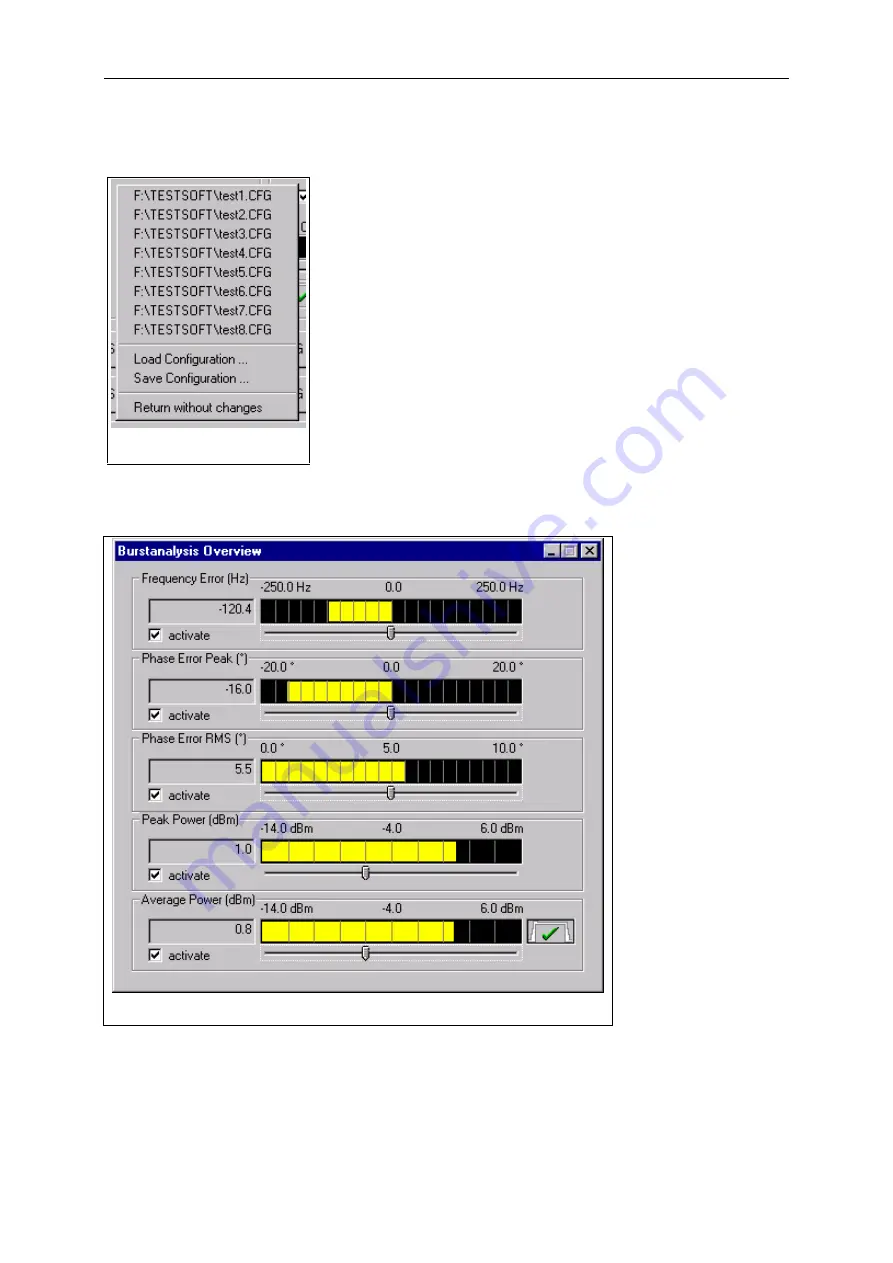
The results of the burst
analysis are displayed in
the popup window Burst
Analysis Overview“ .
The desired
measurement can be
activated by means of
the boxes. The
associated numerical
result is displayed in the
respective field. The
measurement result is
also displayed as
bargraph in the graphics
result display . The
measurement range can
be varied using the
slider below the
bargraph . Moving the
slider to the left reduces
the measurement
range, moving it to the
right extends the range.
The bargraphs for the
different measurements
with range limits are
shown below:
Fig.: Popup menu in GSM
module test dialog
Fig.: Popup menu in GSM module test dialog
Summary of Contents for 1094.0006.50
Page 4: ......
Page 12: ......
Page 22: ......
Page 24: ......
Page 26: ......
Page 28: ......
Page 30: ......
Page 41: ...CTS55 Getting Started With Autotest 1094 0006 55 3 3 E 7...
Page 66: ......
Page 81: ...CTS55 Getting Started With Manual Test 1094 0006 55 6 7 E 6...
Page 83: ...CTS55 Getting Started With Manual Test 1094 0006 55 6 9 E 6...
Page 106: ......
Page 108: ......
Page 196: ......
Page 246: ......
Page 250: ......
Page 254: ......
Page 256: ......
Page 343: ...CTS K6 Windows Application CTSgo 1079 2001 01 87 E 3 Fig CTSgo help window...


