210
Using the Serial Gateway
Section 6-4
Use the following flag to check whether a Serial Gateway response timeout or
send start timeout has occurred.
Step 2: Set the Local Network Tables in the Routing Tables (Using CX-Net).
This step is necessary only when routing table settings are required.
1,2,3...
1.
Using CX-Net, select
Setup
from the Routing Table Menu. Select either
the option
FINS Local
or
FINS Network
using the option button to display
the Routing Table Window.
2.
Click the
Table View
Tab, and create the local network table at the left of
the table.
3.
Set the unit address (see note 1) of the serial port to be treated as a net-
work in the
SIOU
column as a decimal value. Set the network address to
be allocated to the serial port in the
Local Network
column on the right.
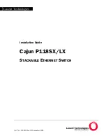
Local Network Table
Example: The following diagram shows the local network table for used to
allocated network address 3 to serial port 1 of a Serial Communications Unit
with unit number 1.
Serial Port Number
The serial port number for the Board/Unit is set as follows:
Serial Communications Units
• Port Number for Serial Port 1
• Port Number for Serial Port 2
Word
Bit
Contents
Board
Unit
Port 1
Port 2
Port 1
Port 2
1908
1918
n+8
n+18
05
Serial Gateway response tim-
eout, Serial Gateway send
start timeout, or other timeout
(protocol macro Tfs, Tfr, or Tr)
1: Timeout; 0: Normal
132
3
Local network table
SIOU
Local Network
Enter the serial port number as a decimal
in the
SIOU
column.
Example: For serial port 1 of the Serial
Communications Unit with unit number 1,
80 hex + 04 hex x 1 = 84 hex = 132
decimal.
To treat the serial port indicated on the
left as a network, enter the network
address to be assigned in the
Local
Network
column.
Example: To assign network address 3,
enter the decimal value 3 in the
Local
Network
column.
Serial port
Serial port number
Example for unit number 1
Serial port 1
80 hex + 04 hex
×
unit
number
80 hex + 04 hex
×
1 = 84 hex
(132 decimal)
Serial port 2
81 hex + 04 hex
×
unit
number
81 hex + 04 hex
×
1 = 85 hex
(133 decimal)
Unit number
0
1
2
3
4
5
6
7
8
9
A
B
C
D
E
F
Hexadecimal
80
84
88
8C
90
94
98
9C
A0
A4
A8
AC
B0
B4
B8
BC
Decimal
128 132 136 140 144
148
152 156 160 164 168
172
176 180 184 188
Unit number
0
1
2
3
4
5
6
7
8
9
A
B
C
D
E
F
Hexadecimal
81
85
89
8D
91
95
99
9D
A1
A5
A9
AD
B1
B5
B9
BD
Decimal
129 133 137 141 145
149
153 157 161 165 169
173
177 181 185 189
Serial Communications Unit
Serial port 1
Serial port 2
Summary of Contents for SYSMAC CJ1W-SCU21-V1
Page 3: ...iv...
Page 5: ...vi...
Page 9: ...x...
Page 15: ...xvi...
Page 89: ...60 Basic Operating Procedure Section 1 9...
Page 151: ...122 RS 232C and RS 422A 485 Wiring Section 3 4...
Page 173: ...144 Host Link Function for Replacing Existing PLCs Section 4 6...
Page 223: ...194 Enhanced Protocol Macro Functions Section 5 6...
Page 277: ...248 Communications Frames Section 6 8...
Page 291: ...262 Basic Operating Procedure in No protocol Mode Section 7 4...
Page 301: ...272 Auxiliary Area and CIO Area Allocations Section 8 3...
Page 391: ...362 Introduction Appendix A...
Page 421: ...392 CompoWay F Master Protocol Appendix B...
Page 513: ...484 E5 K Digital Controller Read Protocol Appendix F...
Page 571: ...542 E5ZE Temperature Controller Write Protocol Appendix I...
Page 587: ...558 E5 J Temperature Controller Protocol Appendix J...
Page 627: ...598 ES100 Digital Controller Protocol Appendix K...
Page 661: ...632 V500 V520 Bar Code Reader Protocol Appendix M...
Page 697: ...668 3Z4L Laser Micrometer Protocol Appendix N...
Page 717: ...688 Visual Inspection System Protocol Appendix O...
Page 755: ...726 V600 V620 ID Controller Protocol Appendix P...
Page 763: ...734 Hayes Modem AT Command Protocol Appendix Q...
Page 767: ...738 Changing Communications Port Settings Using STUP 237 Appendix R...
Page 781: ...752 Revision History...