background image

6   Troubleshooting

6 - 24

NJ-series NJ Robotics CPU Unit User’s Manual (W539)


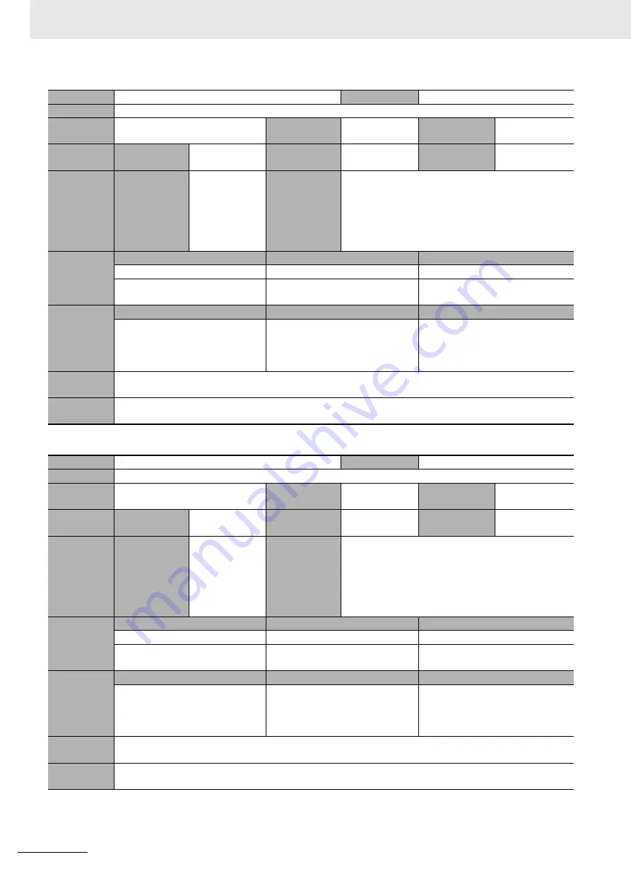
Event name

Acceleration Setting Out of Range

Event code

54230000 hex

Meaning

The parameter specified for the 

Acceleration

 input variable to a motion control instruction is out of range.

Source

Motion Control Function Module

Source details

Axis/axes group

Detection 
timing

At instruction 
execution

Error 
attributes

Level

Minor fault

Recovery

Error reset

Log category

System

Effects

User program

Continues.

Operation

If "axis" is given for the source details, operation is 
not possible for relevant axis. Relevant axis deceler-
ates to a stop if it is in motion.
If "axes group" is given for the source details, opera-
tion is not possible for relevant axes group. Relevant 
axes group decelerates to a stop if it is in motion.

System-
defined 
variables

Variable

Data type

Name

_MC_AX[*].MFaultLvl.Active

BOOL

Axis Minor Fault Occurrence

_MC_GRP[*].MFaultLvl.Active

BOOL

Axes Group Minor Fault Occur-
rence

Cause and
correction

Assumed cause

Correction

Prevention

Instruction input parameter 
exceeded the valid range of the 
input variable.

Correct the parameter so that the 
valid range of the input variable is 
not exceeded for the relevant 
instruction.

Set the input parameter to the 
instruction so that the valid range 
of the input variable is not 
exceeded.

Attached 
information

None

Precautions/
Remarks

None

Event name

Deceleration Setting Out of Range

Event code

54240000 hex

Meaning

The parameter specified for the 

Deceleration

 input variable to a motion control instruction is out of range.

Source

Motion Control Function Module

Source details

Axis/axes group

Detection 
timing

At instruction 
execution

Error 
attributes

Level

Minor fault

Recovery

Error reset

Log category

System

Effects

User program

Continues.

Operation

If "axis" is given for the source details, operation is 
not possible for relevant axis. Relevant axis deceler-
ates to a stop if it is in motion.
If "axes group" is given for the source details, opera-
tion is not possible for relevant axes group. Relevant 
axes group decelerates to a stop if it is in motion.

System-
defined 
variables

Variable

Data type

Name

_MC_AX[*].MFaultLvl.Active

BOOL

Axis Minor Fault Occurrence

_MC_GRP[*].MFaultLvl.Active

BOOL

Axes Group Minor Fault Occur-
rence

Cause and
correction

Assumed cause

Correction

Prevention

Instruction input parameter 
exceeded the valid range of the 
input variable.

Correct the parameter so that the 
valid range of the input variable is 
not exceeded for the relevant 
instruction.

Set the input parameter to the 
instruction so that the valid range 
of the input variable is not 
exceeded.

Attached 
information

None

Precautions/
Remarks

None

Summary of Contents for NJ501-4300

Page 1: ...Machine Automation Controller NJ series NJ Robotics CPU Unit User s Manual W539 E1 04 NJ501 4500 NJ501 4400 NJ501 4320 NJ501 4310 NJ501 4300 CPU Unit ...

Page 2: ... assumed for damages resulting from the use of the information contained in this publication Sysmac and SYSMAC are trademarks or registered trademarks of OMRON Corporation in Japan and other countries for OMRON factory automation products Microsoft Windows Windows Vista Excel and Visual Basic are either registered trademarks or trademarks of Microsoft Corporation in the USA and other countries Eth...

Page 3: ...ed in Related Manuals on page 33 for functions which are common in NJ501 Units including NJ501 1 Units This manual is intended for the following personnel who must also have knowledge of electrical sys tems an electrical engineer or the equivalent Personnel in charge of introducing FA systems Personnel in charge of designing FA systems Personnel in charge of installing and connecting FA systems Pe...

Page 4: ...ontrol Instructions Reference Manual NJ NX series CPU Unit Built in EtherCAT Port User s Manual NJ NX series CPU Unit Built in EtherNet IP Port User s Manual NJ series Database Connection CPU Units User s Manual NJ series NJ Robotics CPU Unit User s Manual NJ NX series Troubleshooting Manual Introduction to NJ series Controllers Setting devices and hardware Using motion control Using EtherCAT Usin...

Page 5: ... error refer to the relevant manuals indicated with mark Purpose of use Manual Basic information NJ series CPU Unit Hardware User s Manual NJ NX series CPU Unit Software User s Manual NJ NX series Instructions Reference Manual NJ NX series CPU Unit Motion Control User s Manual NJ NX series Motion Control Instructions Reference Manual NJ NX series CPU Unit Built in EtherCAT Port User s Manual NJ NX...

Page 6: ...1 Join the Units so that the connectors fit exactly 2 The yellow sliders at the top and bottom of each Unit lock the Units together Move the sliders toward the back of the Units as shown below until they click into place Precautions for Correct Use Precautions for Correct Use 4 3 1 Connecting Controller Components Connector Hook Hook holes Slider Lock Release Move the sliders toward the back until...

Page 7: ...cautions for Correct Use Precautions on what to do and what not to do to ensure proper operation and performance Additional Information Additional information to read as required This information is provided to increase understanding or make operation easier Version Information Information on differences in specifications and functionality for CPU Units Position Interface Units and the Sysmac Stud...

Page 8: ... refers to transferring data from the physical Controller to the Sysmac Studio For the Sysmac Studio synchronization is used to both upload and download data Here synchro nize means to automatically compare the data for the Sysmac Studio on the computer with the data in the physical Controller and transfer the data in the direction that is specified by the user Precaution on Terminology ...

Page 9: ...ser s Manual W539 1 2 3 4 A 5 6 3 4 A 5 I 6 I Overview of NJ Robotics CPU Unit Features of NJ Robotics CPU Unit Setting Robot Functions Robot Instructions Vision Robot Integrated Simulation Troubleshooting A I Appendices Index 1 2 3 I A Sections in this Manual ...

Page 10: ...tions 17 Precautions for Safe Use 19 Precautions for Correct Use 26 Regulations and Standards 28 Using Product Outside Japan 28 Conformance to EC Directives 28 Conformance to Shipbuilding Standards 29 Using Controllers in Robot Systems 29 Software Licenses and Copyrights 29 Versions 30 Confirming Versions 30 Related Manuals 33 Terminology 35 Revision History 37 Section 1 Overview of NJ Robotics CP...

Page 11: ...uctions with Blending Mode 2 37 2 3 13 Trajectory Types for Time specified Motion 2 38 Section 3 Setting Robot Functions 3 1 Setting Group for Robot 3 2 3 1 1 Group Setting Procedures 3 2 3 1 2 Axes Group Settings 3 3 3 1 3 Axis Settings 3 4 3 2 Robot Kinematics Settings 3 9 3 3 Homing 3 10 3 4 Target Position and Direction Setting Method 3 11 3 4 1 Position Settings 3 11 3 4 2 Rotational Axis Con...

Page 12: ...n Procedures 5 5 Section 6 Troubleshooting 6 1 Error Table 6 2 6 2 Error Description 6 22 6 2 1 Interpreting Error Description 6 22 6 2 2 Error Descriptions 6 23 Appendices A 1 Sysmac Studio Robot Additional Option A 2 A 1 1 Enabling the Sysmac Studio Robot Additional Option A 2 A 1 2 Disabling the Sysmac Studio Robot Additional Option A 4 A 1 3 3D Equipment Model Creation Wizard A 6 A 1 4 3D Mach...

Page 13: ...11 CONTENTS NJ series NJ Robotics CPU Unit User s Manual W539 ...

Page 14: ... price of the non complying Product provided that in no event shall Omron be responsible for warranty repair indemnity or any other claims or expenses regarding the Products unless Omron s analysis confirms that the Products were properly handled stored installed and maintained and not subject to contamination abuse misuse or inappropriate modification Return of any Products by Buyer must be appro...

Page 15: ...esponsible for the user s programming of a programmable Product or any consequence thereof Data presented in Omron Company websites catalogs and other materials is provided as a guide for the user in determining suitability and does not constitute a warranty It may represent the result of Omron s test conditions and the user must correlate it to actual application requirements Actual perfor mance ...

Page 16: ...sembly This symbol indicates precautions including warnings The specific operation is shown in and explained in text This example indicates a precaution for electric shock This symbol indicates precautions including warnings The specific operation is shown in and explained in text This example indicates a general precaution This symbol indicates operations that you must do The specific operation i...

Page 17: ...ernal safety measures must be provided to ensure safe operation of the system The CPU Unit will turn OFF all outputs from Basic Output Units in the following cases If an error occurs in the power supply If the power supply connection becomes faulty If a CPU watchdog timer error or CPU reset occurs If a major fault level Controller error occurs While the CPU Unit is on standby until RUN mode is ent...

Page 18: ... take suitable actions such as external fail safe measures and interlock condi tions to monitor the power supply voltage of the external devices as required You must take fail safe measures to ensure safety in the event of incorrect missing or abnormal signals caused by broken signal lines momentary power interruptions or other causes Not doing so may result in serious accidents due to incorrect o...

Page 19: ...screws may result in fire or malfunction Online Editing Execute online editing only after confirming that no adverse effects will be caused by devia tions in the timing of I O If you perform online editing the task execution time may exceed the task period I O may not be refreshed with external devices input signals may not be read and output timing may change Error Message Instructions may result...

Page 20: ...ensors there are differences from the Controller and vision sensors in opera tion and timing After you use the simulation function to debug the user program always check operation and perform adjustments on the physical Controller and vision sensors before you use the user program to operate the controlled system Accidents may occur if the controlled system performs unexpected operation ...

Page 21: ...cables beyond their natural limit Do not place heavy objects on top of the cables or other wiring lines Doing so will damage the cable Mount terminal blocks and connectors only after checking the mounting location carefully Make sure that the terminal blocks expansion cables and other items with locking devices are prop erly locked into place Before you turn ON the power supply be sure to remove a...

Page 22: ...Internal tem perature rise may result in smoking or burning Always input a sinusoidal wave with the frequency that is given in the NJ series CPU Unit Hardware User s Manual Cat No W500 Install external breakers and take other safety measures against short circuiting in external wiring It takes up to approximately 10 to 20 seconds to enter RUN mode after the power is turned ON During that time outp...

Page 23: ...ted devices before you change the settings of an EtherCAT slave or Special Unit If two different function modules are used together such as when you use CJ series Basic Units and EtherCAT slaves take suitable measures in the user program and external controls to ensure that safety is maintained in the controlled system if one of the function modules stops The relevant out puts will stop if a parti...

Page 24: ...RUN mode and then execute forced refreshing from the Sysmac Studio Depending on the difference in the forced status the control system may operate unexpectedly Do not specify the same address for the AT specification for more than one variable Doing so would allow the same entity to be accessed with different variable names which would make the user program more difficult to understand and possibl...

Page 25: ...or a maximum of 45 seconds Before you transfer the user program confirm that the Units will not be adversely affected If the Fail soft Operation Setting parameter is set Stop process data communications will stop for all slaves when an EtherCAT communications error is detected in a slave For this reason if Servo Drives are connected the Servo Drives for all axes will be turned OFF Make sure that t...

Page 26: ...SetKinTransform Set Kinematics Transformation instruction to ensure proper workspace check Check that the work space check function is performed as intended Adjust the home of the robot before you start robot operation Do not operate the robot outside the workspace while the workspace check function is disabled If you do so the robot may be damaged Use the MC_SyncOut End Synchronization instructio...

Page 27: ...ischarge static electricity from your body before starting the procedure After you replace the Battery connect the Sysmac Studio and clear the Low Battery Voltage error Make sure that the required data including the user program configurations setup data variables and memory used for CJ series Units is transferred to the new CPU Unit and externally connected devices before you restart operation Be...

Page 28: ...esult in Unit burning electric shock or failure Do not allow wire clippings shavings or other foreign material to enter any Unit Otherwise Unit burning failure or malfunction may occur Cover the Units or take other suitable countermeasures especially during wiring work For EtherCAT and EtherNet IP use the connection methods and cables that are specified in the NJ NX series CPU Unit Built in EtherC...

Page 29: ...odule Motion control instructions are not executed nor mally if an error occur in slave communications Before you start an MC Test Run make sure that the operation parameters are set correctly Do not download motion control settings during an MC Test Run Do not disconnect the EtherCAT slave cables during operation The outputs will become unstable Set the Servo Drives to stop operation if an error ...

Page 30: ... machine conform to EMC standards 1 Applicable EMC Electromagnetic Compatibility standards are as follows EN 61131 2 and EN 61000 6 2 for EMS Electromagnetic Susceptibility and EN 61131 2 and EN 61000 6 4 for EMI Electromagnetic Interference EN 61000 6 4 Radiated emission is conformed based on 10 m regulations Low Voltage Directive Devices operating at voltages of 50 to 1 000 VAC and 75 to 1 500 V...

Page 31: ... 4400 4500 Controllers do not conform to laws and regulations relating to the safety of industrial robot application When you use the NJ501 4300 4310 4320 4400 4500 Controllers in robot systems that uses indus trial robots be sure to verify the conformance to laws and regulations relating to the safety of industrial robot application Take measures to ensure safety as required This product incorpor...

Page 32: ... functions and performance if they have different unit versions You can confirm versions in the ID information indications on the product or with the Sysmac Studio The version is given on the ID information indication of the products The following figure shows the design of the ID information for NJ Robotics NJ501 4500 CPU Units Confirming Versions Confirming Versions with ID Information Indicatio...

Page 33: ...ight click CPU Expansion Racks under Configurations and Setup and select Edit from the menu The Unit Editor is displayed 2 Right click any open space in the Unit Editor and select Display Production Information The Production Information Dialog Box is displayed Changing Information Displayed in Production Information Dialog Box 1 Select either Show Outline or Show Detail on the lower right corner ...

Page 34: ...Use the following procedure 1 Double click EtherCAT under Configurations and Setup in the Multiview Explorer Or right click EtherCAT under Configurations and Setup and select Edit from the menu The EtherCAT Tab Page is displayed 2 Right click the master in the EtherCAT Tab Page and select Display Production Information The Production Information Dialog Box is displayed The unit version is shown af...

Page 35: ...tions of an NJ NX series CPU Unit Describes the instructions in the instruction set IEC 61131 3 specifications When programming use this manual together with the NJ series CPU Unit Hard ware User s Manual Cat No W500 and NJ NX series CPU Unit Software User s Manual Cat No W501 NJ NX series CPU Unit Motion Control User s Man ual W507 NX701 NJ501 NJ301 NJ101 Learning about motion control settings an...

Page 36: ...ther with the NJ NX series CPU Unit Motion Control User s Manual Cat No W507 and the NJ NX series Motion Control Instructions Reference Manual Cat No W508 NJ NX series Troubleshoot ing Manual W503 NX701 NJ501 NJ301 NJ101 Learning about the errors that may be detected in an NJ NX series Controller Describes concepts on managing errors that may be detected in an NJ NX series Control ler and informat...

Page 37: ...with a T shape and one linear rail instead of two Kinematics In this manual the kinematics refers to a set of expressions required for the follow ing two transforms Transform from the axis coordinate systems ACS of robot links and axes to the robot specific Cartesian coordinate system MCS Transform from the robot specific Cartesian coordinate system MCS to the axis coordinate systems ACS of robot ...

Page 38: ...to 16 Fixed Frame In a Delta robot it refers to a frame to which the axes motors are attached Moving Frame In a Delta robot it refers to a frame driven by the axes motors Robot Tool A mechanical part attached to the robot flange This part performs tasks for work pieces Vision Robot Integrated Simulation A simulation of the pick and place application where this Controller is used in com bination wi...

Page 39: ...mber on the front and back covers of the manual Revision code Date Revised content 01 April 2015 Original production 02 October 2015 Added information on Vision Robot integrated simulation 03 April 2016 Made changes accompanying release of robot version 1 03 of the CPU Unit 04 June 2016 Updated the EtherNet IP logo W539 E1 04 Cat No Revision code ...

Page 40: ...Revision History 38 NJ series NJ Robotics CPU Unit User s Manual W539 ...

Page 41: ...NJ series NJ Robotics CPU Unit 1 1 Features and System Configuration of Unit 1 2 1 1 1 Features of NJ Robotics CPU Unit 1 2 1 1 2 Introduction to the System Configurations 1 4 1 2 Operation Procedure of Unit 1 7 1 3 Specifications of Unit 1 8 1 3 1 Performance Specifications 1 8 1 3 2 Function Specifications 1 8 1 4 Robot Control Configuration 1 10 Overview of NJ Robotics CPU Unit ...

Page 42: ...Studio Automation Software to achieve optimum functionality and ease of operation With a system that is created from Sysmac products you can connect components and operate the system through unified concepts and usability The NJ Robotics CPU Unit has the following features Integrated Sequence Control and Motion Control An NJ series CPU Unit can perform both sequence control and motion control You ...

Page 43: ...s of the NJ series Controllers include operation authority settings and restriction of program execution with IDs Complete Controller Monitoring The CPU Unit monitors events in all parts of the Controller including mounted Units and EtherCAT slaves Troubleshooting information for errors is displayed on the Sysmac Studio or on an HMI Events are also recorded in logs Sysmac Studio Automation Softwar...

Page 44: ...e with very little devi ation Support Software The Support Software is connected to the peripheral USB port on the CPU Unit with a commercially available USB cable You can also connect it through an Ethernet cable that is connected to the built in EtherNet IP port Refer to the NJ NX series CPU Unit Software User s Manual Cat No W501 for details on the con nection with the Support Software 1 1 2 In...

Page 45: ... sensor detects workpieces and the robots put them into boxes Packing 2 The vision sensor detects workpieces conveyed randomly and the robots put them into boxes Packing 3 The vision sensor detects different shapes of workpieces and the robots put them into boxes accord ingly Robot System Configuration Sensor Encoder Box Box Motor Motor Box Box Vision sensor Encoder Puts cylinders Vision sensor En...

Page 46: ...of NJ Robotics CPU Unit 1 6 NJ series NJ Robotics CPU Unit User s Manual W539 Alignment The robots align workpieces conveyed randomly and line them up on another conveyor Motor Motor Vision sensor Encoder Encoder ...

Page 47: ... of the axis coordinate system with that of the motor 1 Create a project Create the EtherCAT Network Configuration Add three axes for the robot 1 Select an axes group used for the robot and assign axes to the logical axes of the group 1 Set the axis parameters Set the Controller Setup Open the MC Test Run Pane Monitor input output signals to check the wiring Perform homing for the robot 1 Create c...

Page 48: ...yor Synchronization Makes the robot to track the workpiece on the conveyor Inverse Kinematics Transforms the coordinates X Y Z Rx Ry Rz of the robot to the axis coordi nates Robot Jogging Jogs the robot Transition You can select the method to make a smooth transition trajectory between robot operation instructions Robot Velocity and Accel eration check Checks robot maximum velocity and acceleratio...

Page 49: ...irtual encoder axes Motion control period The same control period as that is used for the process data communica tions cycle for EtherCAT Use the robot functions with the period of 1 ms 2 ms or 4 ms Cams Number of cam data 65 535 points max per cam table 1 048 560 points max for all cam tables Number of cam tables 640 tables max Cam profile curve Created with the Cam Editor Overwriting cam data Ca...

Page 50: ...rive The NJ Robotics CPU Units are the NJ501 1 Units to which the instructions and data processing for robot operation were added as shown in the following figure With these instructions and data processing the NJ Robotics CPU Unit can perform robot control in the same way as other NJ501 1 Units motion control using function blocks based on IEC 61131 3 For details on the configuration and principl...

Page 51: ...ace Check 2 23 2 3 3 User Coordinate System UCS 2 29 2 3 4 Monitoring 2 30 2 3 5 Time specified Absolute Positioning 2 30 2 3 6 Conveyor Synchronization 2 31 2 3 7 Inverse Kinematics 2 32 2 3 8 Robot Tool 2 32 2 3 9 Robot Jogging 2 34 2 3 10 Checking Maximum Interpolation Velocity and Maximum Interpolation Acceleration Deceleration 2 35 2 3 11 Multi execution of Instructions with Buffered Mode 2 3...

Page 52: ...l W539 2 1 Controllable Robot Types The robot types connectable to the NJ Robotics CPU Unit are Delta3 Delta3R Delta2 Cartesian 3D Cartesian 3D Gantry Cartesian 2D Cartesian 2D Gantry and H Bot The following figure is an example of Delta3 The following figure is an example of Delta2 ...

Page 53: ...s of NJ Robotics CPU Unit NJ series NJ Robotics CPU Unit User s Manual W539 2 1 Controllable Robot Types 2 The following figure is an example of Cartesian 2D The following figure is an example of Cartesian 3D Gantry ...

Page 54: ...2 Features of NJ Robotics CPU Unit 2 4 NJ series NJ Robotics CPU Unit User s Manual W539 The following figure is an example of H bot ...

Page 55: ...ms to control the robots Coordinate Systems for Delta3 2 2 1 Overview of Coordinate Systems Types of Coordinate Systems Coordinate System Description Reference Axis coordinate sys tem ACS The coordinate systems shown with A0 A1 and A2 in the following figure P 2 14 Machine coordinate system MCS The coordinate system shown with Xm Ym and Zm in the following figure P 2 14 User coordinate sys tem UCS...

Page 56: ... Manual W539 Coordinate Systems for Delta3R Axis coordinate system ACS Zm Ym Xm A1 A2 A0 Xu Yu Zu A3 User coordinate system UCS Machine coordinate system MCS Robot TCP Fixed frame Moving frame Xt Yt Yt Zt Zt Yt Zt Xt Zt Yt Tool coordinate system TCSn Tool coordinate system TCS0 ...

Page 57: ...ew of Coordinate Systems Coordinate Systems for Delta2 The figure shows Delta2 viewed from Ym direction Coordinate Systems for Cartesian 3D Xm A0 A1 Zu Xu Zm Machine coordinate system MCS Moving frame Fixed frame User coordinate system UCS Machine coordinate system MCS Xm Ym Zm User coordinate system UCS Xu Yu Zu TCP A0 A1 A2 ...

Page 58: ...e Cartesian 2D kinematics can be arranged in the three coordinate planes Cartesian XY kinematics Cartesian XZ kinematics Cartesian YZ kinematics The figure is an example of Catersian XY kinematics Machine coordinate system MCS Xm Ym Zm User coordinate system UCS Xu Yu Zu TCP A0 A2 A1 A3 Machine coordinate system MCS Xm Ym Zm User coordinate system UCS Xu Yu Zu TCP A0 A1 ...

Page 59: ...4 sub types Direction of TCP movement depends on direction of the axes A0 and A1 and depends on H Bot type H Bot type 1 A0 movement direction A1 movement direction X movement direction Y movement direction Positive Positive Positive No movement Positive Negative No movement Positive Negative Positive No movement Negative Negative Negative Negative No movement Machine coordinate system MCS Xm Ym Zm...

Page 60: ...ection X movement direction Y movement direction Positive Positive Negative No movement Positive Negative No movement Positive Negative Positive No movement Negative Negative Negative Positive No movement Xm Ym Machine coordinate system MCS A0 A1 TCP Xm Ym Machine coordinate system MCS Xu Yu User coordinate system UCS A0 A1 TCP Xm Ym Machine coordinate system MCS Xu Yu User coordinate system UCS A...

Page 61: ...dinate system ACS You must wire so that an axis operates in a downward direction if a positive command velocity is given and the axis operates in an upward direction if a negative command velocity is given A0 movement direction A1 movement direction X movement direction Y movement direction Positive Positive Negative No movement Positive Negative No movement Negative Negative Positive No movement ...

Page 62: ...following table Then positive direction of each axis must follow the positive direction of the corresponding coordinate The following figure is an example of Cartesian 3D Axes Kinematics type Cartesian 3D Cartesian 3D Gantry Cartesian 2D Cartesian 2D Gantry Plane XY Plane XZ Plane YZ A0 X X X X Y X A1 Y X Y Z Z X A2 Z Y Not used Y A3 Not used Z Not used Not used Fixed frame Link 1 Link 2 Negative ...

Page 63: ...axis coordinate system ACS of each axis A0 to A2 and A3 and the directions of the machine coordinate system MCS The figure shows the fixed frame of a Delta3 robot viewed from Zm direction Precautions for Safe Use Set a correct relationship between the direction of commands given by the Controller and the motor rotation direction of the Servo Drive Otherwise the robot may operate unexpectedly Posit...

Page 64: ...rigin of the machine coordinate system to set the target position for robot operation Each robot one axes group has one machine coordinate system The user coordinate system is a Cartesian coordinate system defined by the user Use the rotation and the position relative to the origin of the machine coordinate system to set the origin position Tx Ty Tz Rx Ry Rz of the user coordinate systems The rota...

Page 65: ...et an axes group use the MC_SetKinTransform Set Kinematics Transformation instruction Refer to MC_SetKinTransform on page 4 6 for details on the MC_SetKinTransform Set Kinematics Transformation instruction Select the kinematics type from the following options Delta3 Delta3R Delta2 Cartesian 3D Cartesian 3D Gantry Cartesian 2D Cartesian 2D Gantry and H Bot In this section the settings for each kine...

Page 66: ...f the machine coordinate system MCS Note that if you rotate the machine coordinate system around Z axis with the parameter θ the 0 position of the wrist axis will also be rotated Setting for Delta2 Set the following parameters for Delta2 You cannot use the wrist axis in Delta2 Parameter Description Rf The distance between the center of fixed frame and the axis motor Radius unit mm Rm The distance ...

Page 67: ...cs GrpType When this kinematics is set some functionalities are limited Refer to 4 1 Overview of Robot Instructions on page 4 2 Parameter Description OffX The distance on X between MCS origin and TCP when all axes are 0 unit mm OffY The distance on Y between MCS origin and TCP when all axes are 0 unit mm OffZ The distance on Z between MCS origin and TCP when all axes are 0 unit mm Machine coordina...

Page 68: ...tion OffX The distance on X between MCS origin and TCP when all axes are 0 unit mm OffY The distance on Y between MCS origin and TCP when all axes are 0 unit mm OffZ The distance on Z between MCS origin and TCP when all axes are 0 unit mm Err1 The maximum acceptable error of commanded positions between axes A0 and A1 absolute value unit mm Err2 The maximum acceptable error of actual positions betw...

Page 69: ...the position of A0 and A1 e g MC_GroupSyncMoveAbsolute Precautions for Correct Use When using Cartesian 3D Gantry Kinematics you have to configure parameters Err1 and Err2 Those default values are 0 but cannot be used Program to stop the robot if MC_GroupMon returns FALSE in Valid output because of actual position error A0 A1 In case our gantry robot mechanics cannot work in this simple solution a...

Page 70: ...tesian 2D kinematics configure Plane correctly Otherwise a robot may oper ate unexpectedly Parameter Description Off1 The distance of the first coordinate between MCS origin and TCP when all axes are 0 unit mm Off2 The distance of the second coordinate between MCS origin and TCP when all axes are 0 unit mm Plane Index to defined planes 0 plane XY the first coordinate is X and the second is Y 1 pla...

Page 71: ...s for Correct Use When using Cartesian 2D Gantry Kinematics you have to configure parameters Err1 and Err2 Those default values are 0 but cannot be used Program to stop the robot if MC_GroupMon returns FALSE in Valid output because of actual position error A0 A1 Parameter Description OffX The distance on X between MCS origin and TCP when all axes are 0 unit mm OffY The distance on Y between MCS or...

Page 72: ...CP when all axes are 0 unit mm OffY The distance on Y between MCS origin and TCP when all axes are 0 unit mm Type Type of H Bot 0 H Bot type 1 1 H Bot type 2 2 T Bot type 1 3 T Bot type 2 Item Restriction Maximum length of kinematics parameters Rf must be 2 000 0 mm or less and Lm must be 10 000 0 mm or less Maximum angle between link 1 and link 2 The angle between link 1 and link 2 must be 0 0 to...

Page 73: ...To use the workspace check you need to set the workspace check parameters for the axes group This section describes the settings of the workspace parameters To set an axes group use the MC_SetKinTransform Set Kinematics Transformation instruction Refer to MC_SetKinTransform on page 4 6 for details on the MC_SetKinTransform Set Kinematics Transformation instruction There are five types of workspace...

Page 74: ... of the fourth axis attached to the fixed frame generally has a smaller range of motion than other Delta3 robots In this case you need to adjust workspace parame ters to fit the smaller range of motion Setting Workspace Parameters Parameter Description Zu The front face of the cylinder The position relative to the origin of Z axis unit mm Rcy The radius of the cylinder unit mm Hcy The height of th...

Page 75: ...the origin of Z axis unit mm H The height of the trapezoid unit mm Rtop The radius of the top of the trapezoid unit mm Rbottom The radius of the bottom of the trapezoid unit mm Parameter Description X0 Origin of the workspace X coordinate unit mm Y0 Origin of the workspace Y coordinate unit mm Z0 Origin of the workspace Z coordinate unit mm dx Workspace dimension on the X direction unit mm dy Work...

Page 76: ...rst coordinate direction unit mm d2 Workspace dimension on the second coordinate direction unit mm Plane Index to defined planes 0 plane XY the first coordinate is X and the second is Y 1 plane XZ the first coordinate is X and the second is Z 2 plane YZ the first coordinate is Y and the second is Z Parameter Description X0 Origin of the workspace X coordinate unit mm Y0 Origin of the workspace Y c...

Page 77: ... Therefore the robot target position must be set to positions at least 0 1 mm back from each edge of the workspace If the TCP target position or the TCP actual current position is outside the robot motion range shown below an error is detected and the robot stops immediately The following figure shows an example of Delta3Workspace Robot Motion Range Symbol Description A The workspace set by the MC...

Page 78: ...t tool other than the robot TCP the robot TCP TCP0 placed outside the workspace may cause an error even if the robot tool TCP TCP1 is within the workspace Con firm safety before use The robot tool TCP placed outside the workspace does not cause an error if the robot TCP is within the workspace Precautions on Using Robot Tool TCP0 TCP0 TCP0 TCP0 TCP0 TCP0 P1 P1 TCP1 TCP1 P1 TCP1 TCP0 TCP0 TCP0 TCP0...

Page 79: ...s a clockwise direction from Xu axis to Yu axis when Z axis positive direction is viewed from the origin Set the rotation Ry around Yu1 axis Yu1 is an axis of the user coordinate system Xu1 Yu1 Zu1 created by the rotation Rz The positive direction of rotation Ry is a clockwise direction from Zu1 axis to Xu1 axis when Yu1 axis positive direction is viewed from the origin Set the rotation Rx around ...

Page 80: ... from the current position to the set target position X Y Z Rx Ry Rz in the specified time A robot could be moved using a polynomial function 3rd degree or an Universal CAM Curve function for each Cartesian coordinate it generates a linear movement in 3D Cartesian space Polynomial 3 curve It uses a simple 3rd degree polynomial to interpolate the path between initial position and final position Mod...

Page 81: ...ncOut End Synchronization instruc tion Refer to MC_SyncLinearConveyor on page 4 38 for details on the MC_SyncLinearConveyor Start Conveyor Synchronization instruction and MC_SyncOut on page 4 59 for the MC_SyncOut End Syn chronization instruction You can set offsets during conveyor synchronization If an offset is enabled the offset value is added to the position of the workpiece on the conveyor an...

Page 82: ...MC_InverseKin on page 4 68 for the MC_InverseKin Inverse Kinematics instruction You can define select robot tools for a robot for which the kinematics is already set Use the MC_DefineToolTransform Define Tool Coordinate instruction to make axes group settings Refer to MC_DefineToolTransform on page 4 19 for details on the MC_DefineToolTransform Define Tool Coordinate instruction You can define up ...

Page 83: ...ion P0 of TCP0 is set as follows The following is the current position of TCP1 The target position P2 is set as follows Kinematics type Meaning Delta3 Delta3R Delta2 Target position on X axis Tx mm Valid Valid Valid Target position on Y axis Ty mm Valid Valid Invalid Target position on Z axis Tz mm Valid Valid Valid Target rotational position around X axis Rx degree Invalid Invalid Invalid Target ...

Page 84: ... system UCS or tool coordinate system TCS Use the MC_RobotJog Axes Group Jog instruction to execute jogging Refer to MC_RobotJog on page 4 73 for details on the MC_RobotJog Axes Group Jog instruction During jogging rotation of a rotational axis Rx Ry Rz the position of the selected tool is maintained The following figure shows an example of jogging executed for Rz axis of the active TCP 2 3 9 Robo...

Page 85: ...lation acceleration deceleration check are enabled when the following conditions are met The kinematics are set and the axes group is enabled The maximum interpolation velocity and maximum interpolation acceleration deceleration are set to the values other than 0 0 The background velocity error check and acceleration error check are enabled only for command val ues They are disabled for actual val...

Page 86: ...r instruction execution is completed Checks at Instruction Execution The following two types of checks are performed at instruction execution Sets the values detected as the velocity error and acceleration error for the trajectory data Calculates the command velocity and command acceleration deceleration during instruction exe cution If the calculated value exceeds the maximum interpolation veloci...

Page 87: ...of instructions with the buffered standby mode Refer to 4 2 2 Multi execution in Buffered Mode on page 4 85 and the NJ NX series CPU Unit Motion Control User s Manual Cat No W507 for details The NJ Robotics CPU Units support multi execution of instructions with the blending mixing mode Because the robot control requires smooth transitions you need to select the TransitionMode Transi tion Mode inpu...

Page 88: ...ves This is a type of universal cam curves to that can control acceleration It is recommended to select the modified sine curve to use the transition function Also use this curve for high velocity medium load equipment The modified sine curve is effective in reducing the impact of load variations on the motor 2 3 13 Trajectory Types for Time specified Motion Polynomial 3 Curve Modified Sine Curve ...

Page 89: ...nt velocity curve consists of a combination of sine waves and straight lines This is a type of universal cam curves in which the velocity is constant for the half of the trajectory time period Use this curve for middle velocity high load equipment Modified Constant Velocity Curve 0 1 4 T 1 16T 15 16T 3 4 T T A B C Symbol Meaning A Acceleration deceleration B Velocity C Position ...

Page 90: ...2 Features of NJ Robotics CPU Unit 2 40 NJ series NJ Robotics CPU Unit User s Manual W539 ...

Page 91: ...Robot 3 2 3 1 1 Group Setting Procedures 3 2 3 1 2 Axes Group Settings 3 3 3 1 3 Axis Settings 3 4 3 2 Robot Kinematics Settings 3 9 3 3 Homing 3 10 3 4 Target Position and Direction Setting Method 3 11 3 4 1 Position Settings 3 11 3 4 2 Rotational Axis Control 3 11 3 5 Checking Wiring from the Sysmac Studio 3 14 Setting Robot Functions ...

Page 92: ...1 for how to enable the Sysmac Studio robot options Use the following procedures 1 Create a project 2 Select NJ501 4 for CPU 3 In the EtherCAT Network field register Servo Drives for three axes that are used for the robot 4 Add three axes under Axis Settings 5 Assign a Servo Drive to each axis added in the previous step 6 Add an axes group for the robot 7 Set Axes Group Settings Refer to 3 1 2 Axe...

Page 93: ...r default values are used 3 1 2 Axes Group Settings Axes Group Basic Settings Parameter name Setting Set value Axes Group Use Set whether to enable or disable the axes group Select Used axes group Composition Set the axis composition of the axes group Select 3 axes for using Delta3 robot For using other robots see the following table Composition Axes Sets the axis number to assign it to the axes g...

Page 94: ...polation acceleration deceleration may be exceeded after excessive deceleration during the axes group acceleration deceleration control because stopping at the target position is given priority Interpolation Veloc ity Warning Value Set the percentage of the maximum interpola tion velocity at which to output an interpolation velocity warning Interpolation Accel eration Warning Value Set the percent...

Page 95: ... value Unit of Display Select the display unit Select as the following table according to the intended kinematics type Command Pulse Count Per Motor Rotation Set the number of command pulses per motor rotation according to the encoder resolution 1 1 For example if the encoder resolution is 10 000 pulses per rotation set 10 000 Set the value according to the robot specification Work Travel Dis tanc...

Page 96: ... axis Positive Torque Warning Value Set the torque command value at which to out put a positive torque warning for the axis Negative Torque Warning Value Set the torque command value at which to out put a negative torque warning for the axis Actual Velocity Fil ter Time Constant Set the time period in milliseconds for calculat ing the average travel of the actual velocity In position Range 4 Set t...

Page 97: ...m Positive Torque Limit Set the maximum value of the positive torque limit MaximumNegative Torque Limit Set the maximum value of the negative torque limit Immediate Stop Input Logic Inver sion Set whether to reverse the logic of the immedi ate stop input signal Positive Limit Input Logic Inversion Set whether to reverse the logic of the positive limit input signal Negative Limit Input Logic Inver ...

Page 98: ...Mode if you use the MC_SyncLinearConveyor Start Conveyor Syn chronization instruction Use the unit of mm Set the motor operation to use to determine home Position Count Settings Parameter name Setting Set value Count Mode Set the count mode for the position Select Linear Mode finite length Encoder Type Set the encoder type Set the encoder type to Absolute encoder ABS Homing Settings Parameter name...

Page 99: ...o set the following items in user program to operate robot To set items such as the robot link length and workspace use the MC_SetKinTransform Set Kine matics Transformation instruction while all homes for axes are already determined Refer to MC_SetKinTransform on page 4 6 for details on the MC_SetKinTransform Set Kinematics Transformation instruction ...

Page 100: ...g with the MC Test Run of the Sysmac Studio to set the current position to 0 0 During this operation the Homing Method must be set to Zero position preset By doing this operation the absolute encoder compensation value which is used to set the cur rent position to 0 0 is saved in the NJ series CPU Unit s non volatile memory It is also possible to set the current position to 0 0 with the MC_Home Ho...

Page 101: ... in the axis coordinate system ACS 3 4 1 Position Settings Position Kinematics type Name Meaning Delta3 Delta3R Delta2 Position 0 Target position on X axis mm Used Used Used Position 1 Target position on Y axis mm Used Used Not used Position 2 Target position on Z axis mm Used Used Used Position 3 Target rotational position around X axis degree Not used Not used Not used Position 4 Target rotation...

Page 102: ...lower limit 180 is not reachable therefore the kinematics range of rotation around Z Rz is 180 0 Rz 180 0 Direction input specifies the direction followed by the rotational axes when positioning the robot to the target position Direction input is only applicable to the kinematics that provides orientation Rx Ry Rz _mcPositiveDirection Rotation axis is set to move in the positive direction counter ...

Page 103: ...s the same as that the current position belongs Therefore the robot may take a longer way The following is an example of settings which causes a longer way operation Item Set value Current position 150 0 Target position 150 0 Rotation direction _mcNoDirection Negative Direction Positive Direction 540 360 180 0 180 360 540 180 180 0 Position in Machine Coordinate System MCS degree Current position ...

Page 104: ...ove the moving frame if it is attached This ensures free movement of each axis 2 Check the operation See the above table for check items Refer to Directions of Axis Coordinate System ACS on page 2 11 for details on axis operation direction 3 After you check that all operations are performed as shown in the above table turn OFF the Servo for all axes Attach the moving frame Check item What to check...

Page 105: ...on Robot Instructions 4 5 MC_SetKinTransform 4 6 MC_DefineCoordSystem 4 15 MC_DefineToolTransform 4 19 MC_GroupMon 4 23 MC_MoveTimeAbsolute 4 29 MC_SyncLinearConveyor 4 38 MC_SyncOut 4 59 MC_InverseKin 4 68 MC_RobotJog 4 73 MC_GroupSyncMoveAbsolute 4 82 4 2 Multi execution of Motion Control Instructions 4 84 4 2 1 Multi execution in Aborting Mode 4 84 4 2 2 Multi execution in Buffered Mode 4 85 4 ...

Page 106: ... Transformation MC_DefineCoordSystem Define Coordinate System MC_DefineToolTransform Define Tool Transformation MC_GroupMon Group Monitor MC_MoveTimeAbsolute Time specified Absolute Positioning MC_SyncLinearConveyor Start Conveyor Synchronization MC_SyncOut End Conveyor Synchronization MC_InverseKin Inverse Kinematics MC_RobotJog Robot Jog 4 1 2 Axes Group Instructions Enabled disabled Motion cont...

Page 107: ...ronization instruction MC_RobotJog Axes Group Jog instruction MC_GroupSyncMoveAbsolute Axes Group Cyclic Synchronous Absolute Positioning instruction Use the following three instructions to stop robot operation MC_SyncOut End Synchronization instruction MC_GroupStop Group Stop instruction MC_GroupImmediateStop Axes Group Immediate Stop instruction If you execute the MC_GroupStop Group Stop instruc...

Page 108: ...tion Module An error that occurs in the Built in EtherCAT communications port hardware An error that occurs in an EtheCAT slave While axes operates for a robot instruction the value of the following output variables of the axes group is 0 0 You cannot use these variables for monitoring _MC_GRP 0 31 Cmd Vel _MC_GRP 0 31 Cmd AccDec Additional Information When the robot stops for the MC_Stop Stop ins...

Page 109: ... the robot instructions and the MC_GroupSyncMoveAbsolute Axes Group Cyclic Synchronous Absolute Positioning instruction which is a group motion instruction that you can use for robot operation For details on other instructions refer to the NJ NX series Motion Control Instructions Reference Man ual Cat No W508 ...

Page 110: ...truction Instruction Name FB FUN Graphic expression ST expression MC_SetKinTransform Set Kinemat ics Transfor mation FB MC_SetKinTransform_instance AxesGroup parameter Execute parameter KinTransform parameter Workspace parameter EnableWorkspace parameter MaxVelocityTCP parameter MaxAccelerationTCP parameter MaxDecelerationTCP parameter Done parameter Busy parameter CommandAborted parameter Error p...

Page 111: ... Maximum Interpolation Acceleration is set to 0 interpolation acceleration errors of TCP are not detected Set an acceleration rate for which maxi mum interpolation acceleration errors of TCP 6 are detected unit mm s2 6 A maximum interpolation acceleration error indicates that the maximum interpolation acceleration is exceeded MaxDecelera tionTCP Maximum Interpolation Deceleration LREAL Non nega ti...

Page 112: ...s are completed Busy Executing BOOL TRUE or FALSE TRUE when the instruction is acknowledged CommandAborted Command Aborted BOOL TRUE or FALSE TRUE when the instruction is aborted Error Error BOOL TRUE or FALSE TRUE while there is an error ErrorID Error Code WORD 1 1 Refer to Section 6 Troubleshooting for details Contains the error code when an error occurs A value of 16 0000 indicates normal execu...

Page 113: ...is instruc tions The parameters are set in the Workspace Workspace Parameters input variable even when the EnableWorkspace Enable Workspace input variable is disabled If a Kinematics Initialization Error 571F hex occurs the kinematics parameters previously registered are deleted When this error occurs you must set the kinematics parameters again You can use this instruction only when all the follo...

Page 114: ...C_KIN_REF data type variable Refer to 2 3 1 Kinematics Setting on page 2 15 as well KinType Select the kinematics type KinParam Set the robot parameters depending on robot type Details on _sMC_KIN_REF Name Data type Valid range Description Kinematics Type Selection _eMC_KIN_TYPE 100 _mcDelta3Type1 101 _mcDelta3Type2 102 _mcDelta2Type1 104 _mcCartesian3DType1 1 105 _mcCartesian3DType2 1 106 _mcCart...

Page 115: ...nParam 1 LREAL Full range The distance of the second coordinate between MCS origin and TCP when all axes are 0 Off2 mm KinParam 2 to 7 Reserved LREAL 0 Reserved Name Data type Cartesian2D Gantry and H Bot Valid range Description KinParam 0 LREAL Full range The distance on X between MCS origin and TCP when all axes are 0 OffX mm KinParam 1 LREAL Full range The distance on Y between MCS origin and T...

Page 116: ... axes A0 and A1 absolute value ExpansionParam 1 LREAL 1 0 or Positive Number 1 The maximum acceptable error of actual positions between axes A0 and A1 absolute value ExpansionParam 2 to 7 Reserved LREAL 0 Reserved Name Data type H Bot Valid range Description ExpansionParam 0 LREAL 0 1 2 3 Type of H Bot 0 H Bot type 1 1 H Bot type 2 2 T Bot type 1 3 T Bot type 2 ExpansionParam 1 to 7 Reserved LREAL...

Page 117: ... WorkspaceParam 4 to 7 Reserved LREAL 0 Reserved Name Data type Cartesian3D Valid range Description WorkspaceParam 0 LREAL Full Range Origin of the workspace X coordinate X0 mm WorkspaceParam 1 LREAL Full Range Origin of the workspace Y coordinate Y0 mm WorkspaceParam 2 LREAL Full Range Origin of the workspace Z coordinate Z0 mm WorkspaceParam 3 LREAL Positive number Workspace dimension on the X d...

Page 118: ...0 mm WorkspaceParam 1 LREAL Full Range Origin of the workspace Y coordinate Y0 mm WorkspaceParam 2 LREAL Positive number Workspace dimension on the X direction DX mm WorkspaceParam 3 LREAL Positive number Workspace dimension on the Y direction DY mm WorkspaceParam 4 to 7 Reserved LREAL 0 Reserved Timing Charts Errors Name Data type Cartesian2D Valid range Description 16 0000 Valid Valid Valid Vali...

Page 119: ...parameter Done parameter Busy parameter CommandAborted parameter Error parameter ErrorID parameter Variables Input Variables Name Meaning Data type Valid range Default Description Execute Execute BOOL TRUE or FALSE FALSE The instruction is executed when Execute changes to TRUE CoordTransform Coordinate Transformation _sMC_COOR D_REF Set the user coordinate system UCS Name Meaning Data type Valid r...

Page 120: ...urs A value of 16 0000 indicates normal execution Name Timing for changing to TRUE Timing for changing to FALSE Done When the settings are completed successfully When Execute is TRUE and changes to FALSE After one period when Execute is FALSE Busy When Execute changes to TRUE When Done changes to TRUE When Error changes to TRUE CommandAborted When this instruction is canceled due to an error When ...

Page 121: ...n instruc tion Precautions for Correct Use User coordinate systems UCS are set in relation with a machine coordinate system MCS If you re execute the MC_SetKinTransform Set Kinematics Transformation instruction for a robot you must re define all user coordinate systems for the robot Use the MC_DefineCoordSystem Define Coordinate instruction to set user coordinate sys tems The following are the mem...

Page 122: ...e number or 0 The origin position of the user coordinate system viewed from the origin of Y axis of the machine coordinate system Ty mm Pose 2 LREAL Positive number neg ative number or 0 The origin position of the user coordinate system viewed from the origin of Z axis of the machine coordinate system Tz mm Pose 3 LREAL 180 0 to 180 0 The rotation around X axis of the user coordinate system Rx deg...

Page 123: ...Transform parameter Done parameter Busy parameter CommandAborted parameter Error parameter ErrorID parameter Variables Input Variables Name Meaning Data type Valid range Default Description Execute Execute BOOL TRUE or FALSE FALSE The instruction is executed when Execute changes to TRUE ToolTransform Transform Tool Coordinate System _sMC_TOOL_ COORD_REF Make the settings of the tool coordinate sys...

Page 124: ...urs A value of 16 0000 indicates normal execution Name Timing for changing to TRUE Timing for changing to FALSE Done When the settings are completed successfully When Execute is TRUE and changes to FALSE After one period when Execute is FALSE Busy When Execute changes to TRUE When Done changes to TRUE When Error changes to TRUE CommandAborted When this instruction is canceled due to an error When ...

Page 125: ...MC_SetKinTransform Set Kinematics Transformation instruc tion Precautions for Correct Use Robot tools are set in relation with a machine coordinate system MCS If you re execute the MC_SetKinTransform Set Kinematics Transformation instruction for a robot you must re define all robot tools for the robot Use the MC_DefineToolTransform Define Tool Coordinate instruction to define robot tools The follo...

Page 126: ...tive number nega tive number or 0 The origin position of the tool coordinate system viewed from the robot TCP Ty mm Pose 2 LREAL Positive number nega tive number or 0 The origin position of the tool coordinate system viewed from the robot TCP Tz mm Pose 3 LREAL 180 0 to 180 0 The rotation around X axis of the tool coordinate system Rx degree Pose 4 LREAL 90 0 to 90 0 The rotation around Y axis of ...

Page 127: ...r parameter ErrorID parameter Position parameter Velocity parameter Variables Input Variables Name Meaning Data type Valid range Default Description Enable Enable BOOL TRUE or FALSE FALSE Starts reading the current value when this variable changes to TRUE CoordSystem Coordinate System _eMC_RBT_ COORD_ SYSTEM 1 _mcRBT_MCS 3 _mcRBT_UCS 1 Select the coordinate system 1 Machine coordinate system MCS 3...

Page 128: ...ion Command Cur rent Position ARRAY 0 5 OF LREAL Positive number neg ative number or 0 The command current position of TCP in the specified coordinate system 1 1 Refer to Details on _sMC_POSITION_REF on page 4 26 for details Actual Position Actual Current Position ARRAY 0 5 OF LREAL Positive number neg ative number or 0 The actual current position of TCP in the specified coordinate system 1 Name M...

Page 129: ...P Actual TCP Current Velocity and ActualVelocity Actual Current Velocity are updated each period regardless of whether the axes group is enabled or disabled You can use this instruction only when all the following conditions are met a The kinematics is already set with MC_SetKinTransform Set Kinematics Transformation instruction b Home for all axes registered in the axes group are already defined ...

Page 130: ...osition on axis Z mm CommandPosition 3 LREAL Positive number negative num ber or 0 The command current rotational position around X axis degree CommandPosition 4 LREAL Positive number negative num ber or 0 The command current rotational position around Y axis degree CommandPosition 5 LREAL Positive number negative num ber or 0 The command current rotational position around Z axis degree Name Data ...

Page 131: ...VelocityTCP LREAL Non negative number Unit mm s Name Data type Valid range Description ActualVelocity 0 LREAL Positive number negative num ber or 0 The actual current velocity on X axis Vx mm s ActualVelocity 1 LREAL Positive number negative num ber or 0 The actual current velocity on Y axis Vy mm s ActualVelocity 2 LREAL Positive number negative num ber or 0 The actual current velocity on Z axis ...

Page 132: ...l change to TRUE You can find out the cause of the error by referring to the value output by ErrorID Error Code Timing Charts Errors 16 0000 Enable Busy Error ErrorID Position Velocity Valid Valid No Valid No Valid Valid 16 0000 16 0000 16 0000 Error Code Enable Busy Error ErrorID Position Velocity Valid Valid No Valid No Valid Valid ...

Page 133: ...eter Done parameter Busy parameter Active parameter CommandAborted parameter Error parameter ErrorID parameter Variables Input Variables Name Meaning Data type Valid range Default Description Execute Execute BOOL TRUE or FALSE FALSE The instruction is executed when Execute changes to TRUE Position Target Posi tion ARRAY 0 5 OF LREAL Positive number negative number or 0 0 Set the target position Di...

Page 134: ...s 2 Refer to TransitionMode Transition Mode on page 4 35 for details 3 Refer to TransitionParameter Transition Parameters on page 4 36 for details Name Meaning Data type Valid range Description MoveTraj Type Motion Trajec tory Type Selection _eMC_MOVE_ TRAJ_TYPE 0 _mcPolynomial3 1 _mcRBT_ ModifiedSine Select the trajectory type used to create the command position for each axis 0 Polynomic 3 Curve ...

Page 135: ...iming for changing to TRUE Timing for changing to FALSE Done When the set target time elapsed When Execute is TRUE and changes to FALSE After one period when Execute is FALSE Busy When Execute changes to TRUE When Done changes to TRUE When Error changes to TRUE When CommandAborted changes to TRUE Active When the axes move When Done changes to TRUE When Error changes to TRUE When CommandAborted cha...

Page 136: ...djust the home of the robot before you start robot operation Do not operate the robot outside the workspace when the workspace check function is dis abled If you do so the robot may be damaged If you set 0 for the MaxVelocity Velocity Error Detection Value or MaxAcceleration Acceler ation Error Detection Value parameter for input variables or if you use the default 0 of these variables the velocit...

Page 137: ... X axis mm Position 1 LREAL Positive number nega tive number or 0 The target position on Y axis mm Position 2 LREAL Positive number nega tive number or 0 The target position on Z axis mm Position 3 LREAL 180 0 to 180 0 The target rotational position around X axis Rx degree Position 4 LREAL 180 0 to 180 0 The target rotation position around Y axis Ry degree Position 5 LREAL 180 0 to 180 0 The targe...

Page 138: ...tory Type Selection The workspace check is performed if it is enabled If the created command position is outside the workspace an error occurs and the axis stops When this instruction is executed the maximum values of the command velocity and command acceleration rate are created The instruction checks whether or not these values exceed MaxVeloc ity Velocity Error Detection Value or MaxAcceleratio...

Page 139: ...ction Buffer Mode Selection Description Aborting Cancels the instruction being executed and switches to this instruction If the direction of axis motion is reversed by switching instructions the motion will be reversed according to the Operation Selection at Reversing axis parameter Buffered Buffers this instruction and executes it automatically after the current instruction is com pleted Blending...

Page 140: ... _mcTMStartRemainingTime Start Remaining Time on page 4 88 for details on _mcTM StartRemainingTime Start remaining time TransitionParameter Transition Parameters Name Data type Valid range Description TransitionParameter 0 LREAL Positive number or 0 Transition Start Height The height at which the transition is started mm TransitionParameter 1 to 7 Reserved LREAL 0 Reserved Name Data type Valid ran...

Page 141: ...at you can execute while this instruction is in execution Refer to 4 2 Multi execution of Motion Control Instructions on page 4 84 for details on multi execution of motion control instructions If an error occurs during instruction execution Error will change to TRUE You can find out the cause of the error by referring to the value output by ErrorID Error Code Re execution of Motion Control Instruc...

Page 142: ...sitionParameter parameter InSync parameter Busy parameter Active parameter CommandAborted parameter Error parameter ErrorID parameter TrajStatus parameter Variables Input Variables Name Meaning Data type Valid range Default Description Execute Execute BOOL TRUE or FALSE FALSE The instruction is executed when Execute changes to TRUE InitWorkpiece Position Initial Workpiece Position ARRAY 0 5 OF LRE...

Page 143: ...D UINT 0 to 16 0 Select the ID of the robot tool BufferMode Buffer Mode Selection _eMC_BUFFER_ MODE 0 _mcAborting 1 _mcBuffered 2 _mcBlending Low 3 _mcBlending Previous 4 _mcBlending Next 5 _mcBlending High 0 Select the operation that is per formed when more than one motion instruction are executed 0 Aborting 1 Buffered 2 Blending low 3 Blending previous 4 Blending next 5 Blending high Transition ...

Page 144: ...y errors are detected during command position cre ation 2 2 A velocity error indicates that the command velocity exceeded the specified value If you set this variable to 0 velocity errors are not detected Max Acceleration Acceleration Error Detection Value LREAL Non negative number Set an acceleration rate for which acceler ation errors are detected during command position creation 3 3 An accelera...

Page 145: ...1 Refer to Setting Trajectory on page 4 45 for details on position matching When Error changes to TRUE When CommandAborted changes to TRUE Busy When Execute changes to TRUE When Done changes to TRUE When Error changes to TRUE When CommandAborted changes to TRUE Active When the axes move When Done changes to TRUE When Error changes to TRUE When CommandAborted changes to TRUE CommandAborted When thi...

Page 146: ...celeration Acceleration Error Detection Value If a specified limit is exceeded an error occurs and the axis stops Checks for MaxVelocity Velocity Error Detection Value and MaxAcceleration Acceleration Error Detection Value at instruction execution is performed for a trajectory for the workpiece which is not moved For this reason a velocity error or an acceleration error may be detected in position...

Page 147: ... of these variables the velocity error check or acceleration error check is not performed Prop erly set MaxVelocity Velocity Error Detection Value and MaxAcceleration Acceleration Error Detection Value to avoid an unexpected velocity and acceleration If a robot tool ToolID 1 to 16 other than TCP0 is selected checks for MaxVelocity Velocity Error Detection Value and MaxAcceleration Acceleration Err...

Page 148: ...scription InitWorkpiecePosition 0 LREAL Positive number negative num ber or 0 The current position of workpiece on X axis mm InitWorkpiecePosition 1 LREAL Positive number negative num ber or 0 The current position of workpiece on Y axis mm InitWorkpiecePosition 2 LREAL Positive number negative num ber or 0 The current position of workpiece on Z axis mm InitWorkpiecePosition 3 LREAL 180 0 to 180 0 ...

Page 149: ... set Direction input is not used For Delta 3R meaning of Direction input is below Use TrajData Trajectory Data to set the parameters for creating the trajectory along which the robot tracks the workpiece This section describes the relationship between the trajectory and the setting values for a polynomic 3 curve The following symbols are used in this description Position Kinematics type Name Carte...

Page 150: ...oves down along Z axis At this moment the robot does not stop Symbol Description T1 Trajectory target time unit ms T2 T3 Ttrans1 Trajectory transition unit Ttrans2 H1 The travel distance on the trajectory in Z axis direc tion in the machine coordinate system unit mm Symbol Description A The current position of the robot B T1 Ttrans1 C T1 H1 D T2 E T3 T3 Ttrans2 F InSync changes to TRUE when the po...

Page 151: ...sive Following error error code 6702 hex occurs If H1 0 0 and T1 0 Motion control period Range of difference 500 μs 0 1 mm max 1 ms 0 1 mm max 2 ms 0 2 mm max 4 ms 0 4 mm max Symbol Description A The current position of the robot B T1 Ttrans1 C T1 H1 D T2 E T3 T3 Ttrans2 F InSync changes to TRUE when the position of the robot and the position of the workpiece match G T3 H T3 Ttrans2 I The trajecto...

Page 152: ...al current position X Y of the workpiece If the difference is within the following range InSync changes to TRUE If the difference exceeds the following range an error occurs and the axis stops At this moment the Workpiece Synchronization Excessive Following error error code 6702 hex occurs When T1 0 Motion control period Range of difference 500 μs 0 1 mm max 1 ms 0 1 mm max 2 ms 0 2 mm max 4 ms 0 ...

Page 153: ... 2 Rotation finishes at the end of the phase which is specified as Final Phase The parameter Rotation Transition 2 sets the Final Phase It is only possible to set phases 0 to 4 because at the end of phase 4 synchronization is reached and orientation of the robot must be already achieved The following are the limitations of Rotation Transitions In case Rotation Transition 1 and Rotation Transition ...

Page 154: ...he trajectory type that is used to create the command position for synchronization with the conveyor Details on _sMC_SYNC_TRAJ_REF Name Data type Valid range Description SyncTrajType _eMC_SYNC_ TRAJ_TYPE 0 _mcFlatTraj 2 _mcFlatTrajModSine 3 _mcFlatTrajModConstVel 0 Polynomic 3 Curve 2 Modified Sine Curve 3 Modified Constant Velocity Curve Rz 45 Position profile 0 VRz s 0 s Velocity profile Ph 1 Ph...

Page 155: ...mand position creation A velocity error indicates that the command velocity exceeded the specified value If you set this variable to 0 velocity errors are not detected Name Data type Valid range Description TrajTime 0 UINT Non negative number T1 ms TrajTime 1 UINT Positive number T2 ms TrajTime 2 UINT Positive number T3 ms TrajTime 3 to 7 Reserved UINT 0 Reserved Name Data type Valid range Descrip...

Page 156: ...appens for T3 T3 Ttrans2 See the phase of MC_SyncLinearConveyor with transition at 100 on the following table Name Data type Valid range Description MaxAcceleration LREAL Non negative number Unit mm s2 Details on _sMC_SYNC_TRAJ_STATUS Name RemainTime Gives the remaining of the Trajectory Target Time T1 T2 T3 This value is calculated by a subtraction from the Trajectory Target Time T1 T2 T3 unit ms...

Page 157: ...fferent than 6 error occurs Precautions for Correct Use You can enable offsets only when TCP is in synchronization with the workpiece If you enable offsets when synchronization is not performed an error will occur If the offset is changed from Disabled to Enabled TCP may move suddenly depending on the offset value PositionOffset Offset Value To set the offset value set the position X Y Z in the co...

Page 158: ...esian 3D Gantry Cartesian 2D Cartesian 2D Gantry H Bot Plane XY Plane XZ Plane YZ PositionOffset 0 Valid Valid Valid Invalid Valid PositionOffset 1 Valid Valid Invalid Valid Valid PositionOffset 2 Valid Invalid Valid Valid Invalid PositionOffset 3 Invalid Invalid Invalid PositionOffset 4 to 5 Reserved Invalid Invalid Invalid Name Offset Enabled Disabled Disabled Enabled Enabled Enabled Disabled Po...

Page 159: ...er coordinate system UCS are speci fied Specifying Machine Coordinate System MCS Align Xm and the conveyor axis in the same direction as shown in the following figure Xm Ym and Zm represent the machine coordinate system MCS Specifying User Coordinate System UCS Align Xu and the conveyor axis in the same direction as shown in the following figure Xm Ym and Zm represent the machine coordinate system...

Page 160: ...iption Aborting Cancels the instruction being executed and switches to this instruction If the direction of axis motion is reversed by switching instructions the motion will be reversed according to the Operation Selection at Reversing axis parameter Buffered Buffers this instruction and executes it automatically after the current instruction is com pleted Blending Starts the buffered instruction ...

Page 161: ...iningTime Start Remaining Time on page 4 88 for details on _mcTM StartRemainingTime Start remaining time TransitionParameter Transition Parameters Name Data type Valid range Description TransitionParameter 0 LREAL Positive number or 0 Transition Start Height The height at which the transition is started mm TransitionParameter 1 to 7 Reserved LREAL 0 Reserved Name Data type Valid range Description ...

Page 162: ...te while this instruction is in execution Refer to 4 2 Multi execution of Motion Control Instructions on page 4 84 for details on multi execution of motion control instructions If an error occurs during instruction execution Error will change to TRUE You can find out the cause of the error by referring to the value output by ErrorID Error Code Re execution of Motion Control Instructions Multi exec...

Page 163: ...ied it is maintained to the default value FALSE so deceleration is never triggered Conversely to use this instruction in CPU Unit version 1 10 or before with an existing project whose CPU Unit version is 1 11 or later user has to update the ladder programs to remove DecelerationTrigger input and rebuild them from Sysmac Studio Instruction Name FB FUN Graphic expression ST expression MC_SyncOut End...

Page 164: ...Selection _eMC_SYNC_ STOP_TYPE 0 _mcSyncStop 1 _mcRBT_ ImmediateStop 2 _mcSync DecelerationStop 4 Select the trajectory type that is used to cre ate the command position for cancellation of synchronization with the conveyor 0 Synchronized stop 1 Immediate stop 2 Synchronized stop with Deceleration TrajTime Trajectory Target Time ARRAY 0 7 OF UINT Set the target time for a synchronized stop 1 1 Ref...

Page 165: ...ing to FALSE Done When the set target time elapsed When Execute is TRUE and changes to FALSE After one period when Execute is FALSE Busy When Execute changes to TRUE When Done changes to TRUE When Error changes to TRUE When CommandAborted changes to TRUE CommandAborted When this instruction is aborted because another motion control instruction was executed with the Buffer Mode set to Aborting When...

Page 166: ... all axes registered in the axes group e The axes group is enabled f If you select a synchronized stop Phase of the trajectory status must be 6 This is checked only when the instruction is executed g If you select an immediate stop MC_SyncLinearConveyor Start Conveyor Synchronization instruction execution must be in progress Precautions for Safe Use Adjust the home of the robot before you start ro...

Page 167: ... When the operation switches from the MC_SyncLinearConveyor Start Conveyor Synchronization instruction to the MC_SyncOut End Synchronization instruction transition velocities are created with command positions If you select Synchronized stop with Deceleration you can execute this instruction only when Phase of the trajectory status is 6 too The details on stopping operation and parameter setting a...

Page 168: ...to unexpected long time the robot may reach out of the workspace during deceleration Do not disable workspace check Additional Information If you select _mcSyncStop or _mcSyncDecelerationStop for SyncStopType and set the value of H4 to 0 the robot performs synchronized motion according to the value of T4 and then stops Velocity in X axis Acceleration in X Jerk in X Velocity in Z axis T4 T5 Synchro...

Page 169: ...nStop 1 1 A CPU Unit with robot version 1 03 or later and Sysmac Studio version 1 15 or higher are required to use this sync stop type For any previous version combinations this type does not exist Select the trajectory type that is used to create the command position for cancel lation of synchronization with the con veyor 0 Synchronized stop 1 Immediate stop 2 Synchronized stop with Deceleration ...

Page 170: ...n is attempted and all axes in motion stop There are restrictions on the instructions that you can execute while this instruction is in execution Refer to 4 2 Multi execution of Motion Control Instructions on page 4 84 for details on multi execution of motion control instructions Name Data type Valid range Description MaxAcceleration LREAL Non negative number Unit mm s2 Timing Charts Re execution ...

Page 171: ...l W539 MC_SyncOut 4 Function If an error occurs during instruction execution Error will change to TRUE You can find out the cause of the error by referring to the value output by ErrorID Error Code Errors Busy Done CommandAborted Error 16 0000 ErrorID Execute Error Code ...

Page 172: ...y parameter Error parameter ErrorID parameter AxesPosition parameter OutWorkspace parameter Variables Input Variables Name Meaning Data type Valid range Default Description Enable Enable BOOL TRUE or FALSE FALSE Transforms a target position into axes target positions when Enable changes to TRUE Position Target Posi tion ARRAY 0 5 OF LREAL Positive number negative number or 0 0 Set the target posit...

Page 173: ...r FALSE TRUE while there is an error ErrorID Error Code WORD 1 1 Refer to Section 6 Troubleshooting for details Contains the error code when an error occurs A value of 16 0000 indicates normal execution AxesPosition Axes Target Position ARRAY 0 5 OF LREAL Positive number neg ative number or 0 Contains axes target positions that are trans formed from a target position in the machine coordinate syst...

Page 174: ...inate system degree Position 4 LREAL Greater than 180 0 less than or equal to 180 0 The target rotational position around Y axis in the machine coordinate system degree Position 5 LREAL Greater than 180 0 less than or equal to 180 0 The target rotational position around Z axis in the machine coordinate system degree Position Kinematics type Name Description Delta3 Delta3R Delta2 Position 0 The tar...

Page 175: ...umber or 0 The target position in the axis coordinate sys tem for A3 axis degree or mm depending on KinType AxesPosition 4 to 5 Reserved LREAL 0 Reserved AxesPosition Kinematics type Name Description Delta3 Delta3R Delta2 AxesPosition 0 The target position in the axis coordi nate system for A0 axis degree or mm depending on KinType Used Used Used AxesPosition 1 The target position in the axis coor...

Page 176: ...e error by referring to the value output by ErrorID Error Code Timing Charts Errors 16 0000 In the workspace In the workspace In the workspace In the workspace In the workspace In the workspace Out of workspace Enable Valid Busy OutWorkspace Error ErrorID Position in MCS No Valid Valid Position in ACS 16 0000 Error Code Enable Valid Busy Error ErrorID No Valid Valid Position in ACS ...

Page 177: ...er Acceleration parameter Deceleration parameter JogMode parameter CSID parameter ToolID parameter Busy parameter CommandAborted parameter Error parameter ErrorID parameter Variables Input Variables Name Meaning Data type Valid range Default Description Positive Enable_X X Positive Enable BOOL TRUE or FALSE FALSE When this variable changes to TRUE the robot starts moving in the X axis positive dir...

Page 178: ... variable changes to TRUE the robot starts moving in the positive rotation direction around Y axis When it changes to FALSE the robot stops moving Negative Enable_RY Y Rotate Neg ative Enable BOOL TRUE or FALSE FALSE When this variable changes to TRUE the robot starts moving in the negative rotation direction around Y axis When it changes to FALSE the robot stops moving Positive Enable_RZ Z Rotate...

Page 179: ...ccurs A value of 16 0000 indicates normal execution Name Timing for changing to TRUE Timing for changing to FALSE Busy When Enable changes to TRUE When Error changes to TRUE When all Enable variables change to FALSE CommandAborted When this instruction is aborted because another motion control instruction was executed with the Buffer Mode set to Aborting When this instruction is canceled due to an...

Page 180: ... Selection as shown below Table above is based on machine coordinate system MCS When a user coordinate system is used positions of the axis for which Rotate Enable is set are transformed into positions in the machine coordinate system After the transformation invalid values that are determined based on this table are ignored In Out Variables Name Meaning Data type Valid range Description AxesGroup...

Page 181: ... rate to reach target velocity for the selected robot components It is divided in Acceleration for X Y and Z translation and Acceleration for RX RY and RZ rotation Deceleration input sets the deceleration rate to stop from target velocity for the selected robot compo nents It is divided in Deceleration for X Y and Z translation and Deceleration for RX RY and RZ rotation When the Acceleration Accel...

Page 182: ...selected robot tool If you select _mcUserMode user mode for JogMode Jog Mode Selection you need to set the user coordinate system you use in CSID Coordinate System ID If you do not select _mcUserMode user mode for JogMode Jog Mode Selection the variable CSID Coordinate System ID is ignored The value that was set in CSID Coordinate System ID when Enable changed to TRUE is used while this instructio...

Page 183: ...al W539 MC_RobotJog 4 Function 1 Decelerates to a stop due to an error in another instruction Timing Charts 16 0000 PositiveEnable_X NegativeEnable_X Busy CommandAborted Error ErrorID 1 Target velocity Time Acceleration rate Deceleration rate Velocity in XMCS direction ...

Page 184: ...on Acceleration Rate and Deceleration Deceleration Rate The deceleration rate for reversing and the acceleration rate after reversing are determined by the variables that are input when NegativeEnable Negative Direction Enable changed to TRUE regardless of the value of the Operation Selection at Reversing axis parameter If a PositiveEnable Positive Direction Enable variable changes to TRUE during ...

Page 185: ... occurs during instruction execution Error will change to TRUE You can find out the cause of the error by referring to the value output by ErrorID Error Code Errors PositiveEnable_X NegativeEnable_X PositiveEnable_Y PositiveEnable_Z NegativeEnable_Z Busy Error Code NegativeEnable_Y CommandAborted Error ErrorID ...

Page 186: ...he kinematics for the axes group 3 Execute the MC_GroupEnable Enable Axes Group instruction Enable the axes group 4 Calculate the trajectory Create the target positions Xi Yi Zi in the machine coordinate system MCS After this execute the calculation each period 5 Execute the MC_InverseKin Inverse Kinematics instruction Transform the target position Xi Yi Zi into the target value A0i A1i A2i in the...

Page 187: ...MC_GroupSyncMoveAbsolute Axes Group Cyclic Synchro nous Absolute Positioning instruction the workspace check is not performed Also checks for the following variables that are set with the MC_SetKinTransform Set Kinematics Transforma tion instruction are not performed MaxVelocityTCP Maximum Interpolation Velocity MaxAc celerationTCP Maximum Interpolation Acceleration and MaxDecelerationTCP Maximum ...

Page 188: ...s currently executed is aborted Note that command velocity output starts from the initial value 0 3 Error An error is detected when the next instruction is executed and the axes stop immediately 4 2 1 Multi execution in Aborting Mode The current instruction MC_Move TimeAbsolute MC_Sync Linear Conveyor 1 1 When Phase is not 6 MC_Sync Linear Conveyor 2 2 When Phase is 6 MC_Sync Out 3 3 When SyncStop...

Page 189: ...hich is currently executed is aborted 2 Error An error is detected when the next instruction is executed and the axes stop immediately 4 2 2 Multi execution in Buffered Mode The current instruction MC_Move TimeAbsolute MC_Sync Linear Conveyor 1 1 When Phase is not 6 MC_Sync Linear Conveyor 2 2 When Phase is 6 MC_Sync Out 3 3 When SyncStopType Synch Stop Type Selection is set to 0 Synchronized stop...

Page 190: ...rt height the next instruction is blended with the current instruction The value of Transition Start Height set in the TransitionParameter Transition Parameters input vari able determines the blended part of the instruction Transition starts when the travel distance in Z axis direction exceeds the Transition Start Height in the current instruction The transition ends at the same time as the curren...

Page 191: ...r Syn chronization instruction and all the following conditions are met The operation direction along Z axis in the machine coordinate system MCS is different for the current and buffered instructions and operation that meets the above conditions is completed earlier than the transition Trajectory in Conveyor Synchronization The motion of current instruction in the conveyor direction is decelerate...

Page 192: ...r Synchronization is exe cuted as the buffered instruction the duration of buffered instruction is equal to T1 T2 T3 T3 Ttrans2 When _mcTMStartRemainingTime Start remaining time is used the values of velocity acceleration rate and deceleration rate may be greater than that of the current and next instructions that are executed separately If they must be used be careful of the operation When MC_Syn...

Page 193: ...on The motion of current instruction in the conveyor direction is decelerated so that the instruction is blended with the next instruction Symbol Description A The current instruction B The next instruction C The time at which transition is started Symbol Description A The conveyor synchronization instruction which is currently exe cuted B The next instruction C The time at which transition is sta...

Page 194: ...n going has already finished Remaining time of current instruction Maximum value of remaining time of cur rent instruction and specified decelera tion target time Maximum value of remaining times of movement in Z axis and deceleration Remaining time in Z axis Synchronized stop Synchronized stop with Deceleration Deceleration by DecelerationTrigger has not started yet is on going has already finish...

Page 195: ...or the ResetMCError Reset Motion Control Error instruction is executed while the axes group is in a GroupEnable state 5 An ErrorStop state is entered from any other state It is entered even if an error occurs while the axes group is in a GroupDisable state 6 The axes group enters a Disabled state if the MC_GroupReset Group Reset instruction or the ResetMCEr ror Reset Motion Control Error instructi...

Page 196: ...gical axis A0 MC_Axis000 A1 MC_Axis001 A2 MC_Axis002 A3 MC_Axis003 Conveyor axis MC_Axis004 Power_Enable Ins_Power0 Error Axis Axis Enable Status Busy MC_Power ErrorID MC_Axis000 MC_Axis000 Power0_Status Power0_Busy Power0_Error Power0_ErrorID Ins_Power1 Error Axis Axis Enable Status Busy MC_Power ErrorID MC_Axis001 MC_Axis001 Power1_Status Power1_Busy Power1_Error Power1_ErrorID Ins_Power2 Error ...

Page 197: ...Done SKT_Busy CommandAborted SKT_CommandAborted SKT_Error SKT_ErrorID Ins_GroupEnable Error AxesGroup AxesGroup Execute Done Busy MC_GroupEnable ErrorID MC_Group000 MC_Group000 GE_Done GE_Busy CommandAborted GE_CommandAborted GE_Error GE_ErrorID Set kinematics transform Enable axes group DCS_Exe DTT_Exe Ins_DefineCoordSystem Error AxesGroup CoordTransform AxesGroup Execute Done Busy MC_DefineCoord...

Page 198: ...esGroup TrajData AxesGroup Execute Done Busy MC_SyncOut ErrorID MC_Group000 SyncOut_TD MC_Group000 SyncOut_Done SyncOut_Busy CommandAborted SyncOut_CommandAborted SyncOut_Error SyncOut_ErrorID End_Conveyor Ins_SyncLinearConveyor Error AxesGroup AxesGroup ConveyorAxis ConveyorAxis Execute InSync Busy MC_SyncLinearConveyor ErrorID MC_Group000 MC_Axis004 InitWorkpiecePosition SLC_IWP TrajData SLC_TD ...

Page 199: ...integrated simulation a function to simulate the pick and place application where this Controller is used in combination with one or more vision sensors and robots 5 1 Overview of Simulation 5 2 5 2 Models that Support Simulation 5 3 5 3 Simulation Procedures 5 5 Vision Robot Integrated Simulation ...

Page 200: ...ntegrated simulation you can simulate the operation of the pick and place appli cation in 3D This leads to the reduction of time for the verification in the most upstream because the actual device environment is no longer necessary To perform the Vision Robot integrated simulation you need to purchase the Robot Additional Option a Sysmac Studio option Refer to A 1 Sysmac Studio Robot Additional Op...

Page 201: ...dels and the number of supported units are listed in the following table Servo for Driving Robots The compatible models are listed in the following table Series Product Model Version NJ5 Robotics NJ501 4300 4400 4500 CPU Units Version 1 10 or later Robots Version 1 02 or later NJ501 4310 Robotics DB Con nection NJ501 4320 Series Model Qty FH FH 1 FH 3 1 sensor for each conveyor for picking Series ...

Page 202: ... specify depends on the number of robots HMI You can perform a simulation of HMI projects along with a Vision Robot integrated simulation The compatible models are listed in the following table Conveyor drive source Device to detect the conveyor travel distance 1 G5 series Servo Drive and Servomotor G5 series Servomotor encoder 2 Any Encoder connected to an encoder input slave GX EC 3 Any Encoder ...

Page 203: ...rkpieces captured by the vision sensor Use the dedicated setup wizard to set the 3D equipment model for the pick and place application On the Sysmac Studio perform simulations for the vision sensor and the Robotics CPU Unit at the same time and debug the user program After you debug the user program save the trace data for the equipment model Load the trace data that you saved and execute 3D motio...

Page 204: ...5 Vision Robot Integrated Simulation 5 6 NJ series NJ Robotics CPU Unit User s Manual W539 ...

Page 205: ...User s Manual W539 This section describes the errors events that can occur and the corrections for them 6 1 Error Table 6 2 6 2 Error Description 6 22 6 2 1 Interpreting Error Description 6 22 6 2 2 Error Descriptions 6 23 Troubleshooting ...

Page 206: ...el Min Minor fault level Obs Observation Info Information Errors Related to Robot Control Function Event code Event name Meaning Assumed cause Level Reference Maj Prt Min Obs Info 54220000 hex Target Velocity Set ting Out of Range The parameter specified for the Velocity input variable to a motion control instruction is out of range Instruction input parameter exceeded the valid range of the input...

Page 207: ...6 543B0000 hex Motion Control Instruction Re executio n Disabled An attempt was made to re execute a motion control instruction that cannot be re executed A motion control instruction that cannot be re executed was re executed P 6 27 543C0000 hex Motion Control Instruction Multi executi on Disabled Multiple functions that cannot be executed simultaneouslywere executed for the same target MC common...

Page 208: ...Error A motion instruction was executed for an axes group while the MC_Stop instruction was being executed for a composition axis A motion instruction was executed for an axes group while the MC_Stop instruc tion was being executed for a composition axis P 6 32 54430000 hex Motion Control Instruction Multi executi on Buffer Limit Exceeded The number of motion control instructions that is buffered ...

Page 209: ...fined home One of the following robot instructions was executed for an axes group that includes a logical axis with no defined home MC_SetKinTransform MC_MoveTimeAbsolute MC_SyncLinearConveyor MC_SyncOut MC_GroupMon MC_RobotJog P 6 34 54780000 hex Target Position Setting Out of Range The parameter specified for the Position input vari able to a motion control instruction is out of range Instructio...

Page 210: ...Param or ExpansionParam specified for the KinTransform input variable to a motion control instruction is out of range KinParam is outside the setting range ExpansionParam is outside the setting range P 6 38 57090000 hex Workspace Type Out of Range WorkspaceType specified for the Workspace input variable to a motion control instruction is out of range WorkspaceType is outside the setting range P 6 ...

Page 211: ...ion for which direct kinematics calculation cannot be performed Inverse kinematics calculation cannot be performed for the target position specified in the machine coordinate system P 6 41 57100000 hex Kinematics Transform Not Set The kinematics transform is not set for the specified axes group The kinematics transform is not set for the axes group P 6 41 57110000 hex Target Position Out of Range ...

Page 212: ...input variable to a motion control instruction is out of range TrajDistance is outside the setting range P 6 45 57190000 hex Initial Workpiece Position Outside Workspace The position of the workpiece specified for the InitWorkpiecePositi on input variable to a motion control instruction is outside the workspace InitWorkpiecePosition is outside the workspace P 6 45 571A0000 hex Invalid Conveyor Axi...

Page 213: ...ned by the MC_DefineToolTransform instruction P 6 49 57330000 hex Tool Parameter Out of Range The transform parameter specified for the ToolTransform input variable to a motion control instruction is out of range The transform parameter is outside the setting range P 6 49 57340000 hex Unsupported Transition Data The transition mode specified for the TransitionMode input variable to a motion contro...

Page 214: ...setting range P 6 52 57450000 hex Initial Workpiece Position Out of Range The InitWorkpiecePositi on input variable to the MC_SyncLinearCon veyor instruction is out of range The InitWorkpiecePosition input variable to the MC_SyncLinearConveyor instruction is outside the setting range P 6 52 57460000 hex Maximum Interpolation Velocity Out of Range The MaxVelocityTCP input variable to the MC_SetKinT...

Page 215: ...negative limit input was ON P 6 56 64590000 hex Home Undefined during Coordinated Motion Home of the logical axis became undefined during axes group motion or while decelerating to a stop The command position or actual position overflowed or underflowed for a logical axis in an axes group motion or a logical axis that was decelerating to a stop and the home definition was lost A slave communicatio...

Page 216: ... too low P 6 60 67000000 hex Command Position Outside Workspace The command position is outside the workspace The specified trajectory data is incorrect P 6 60 67010000 hex Current Position Outside Workspace The current position was outside the workspace when an instruction was executed The current position was outside the workspace when one of the following instructions was executed MC_MoveTimeAb...

Page 217: ...cations are not established for the conveyor axis The slave of the conveyor axis was disconnected An Absolute Encoder Current Position Calculation Failed error 64580000 hex was detected for the conveyor axis P 6 65 94230000 hex Transition Parameter Adjusted The specified TransitionParameter input variable was adjusted before transition started The transition start condition specified for Transitio...

Page 218: ...on control instruction is out of range Instruction input parameter exceeded the valid range of the input variable P 6 69 54015432 hex Transition Mode Selec tion Out of Range The parameter specified for the TransitionMode input variable to a motion control instruction is out of range Instruction input parameter exceeded the valid range of the input variable _mcAborting or _mcBuffered was specified ...

Page 219: ...g P 6 74 54015441 hex Impossible Axis Operation Specified when the Servo is OFF A motion instruction was executed for an axis for which the Servo is OFF A motion instruction was executed for an axis for which the Servo is OFF A zero position preset was performed with the MC_Home or MC_HomeW ithParameter instruction for an axis for which EtherCAT process data communica tions are not established P 6...

Page 220: ...for an axes group that includes a logical axis with no defined home MC_SetKinTransform MC_MoveTimeAbsolute MC_SyncLinearConveyor MC_SyncOut MC_GroupMon MC_RobotJog P 6 79 54015478 hex Target Position Setting Out of Range The parameter specified for the Position input vari able to a motion control instruction is out of range Instruction input parameter exceeded the valid range of the input variable...

Page 221: ...tting range P 6 83 5401570B hex Invalid Coordinate System Number The coordinate system ID specified for the CSID input variable to a motion control instruction is out of range or not defined The coordinate system ID is outside the setting range The specified coordinate system ID is not defined by the MC_DefineCoordSystem instruction P 6 84 5401570C hex Coordinate Transformati on Parameter Out of R...

Page 222: ...f range TrajTime is outside the setting range P 6 88 54015715 hex Trajectory Type Out of Range MoveTrajType specified for the TrajData input variable to a motion control instruction is out of range MoveTrajType or SyncTrajType is outside the setting range P 6 88 54015716 hex Trajectory Transition Out of Range TrajTransition specified for the TrajData input variable to a motion control instruction ...

Page 223: ...ceeded the limit The number kinematics set by the MC_SetKinTransform instruction exceeded the limit P 6 93 5401571F hex Kinematics Initialization Error Kinematics initialization failed One of the robot axes A0 to A3 is stopped at the position for which direct kinematics calculation cannot be performed P 6 94 54015732 hex Invalid Tool Number The tool ID specified for the ToolID input variable to a ...

Page 224: ...P 6 99 54015748 hex Maximum Interpolation Deceleration Out of Range The MaxDecelerationTC P input variable to the MC_SetKinTransfor m instruction is out of range The MaxDecelerationTCP input variable to the MC_SetKinTransform instruction is outside the setting range P 6 100 54016443 hex Positive Limit Input An instruction was executed for a motion in the positive direction when the positive limit ...

Page 225: ...ace The current position was outside the workspace when an instruction was executed The current position was outside the workspace when one of the following instructions was executed MC_MoveTimeAbsolute MC_SyncLinearConveyor MC_SyncOut MC_RobotJog P 6 103 Event code Event name Meaning Assumed cause Level Reference Maj Prt Min Obs Info ...

Page 226: ...epends on cause The recovery method depends on the cause of the error Log category Tells which log the error is saved in 3 3 One of the following System System event log Access Access event log Effects User program Tells what will happen to exe cution of the user program 4 4 One of the following Continues Execution of the user program will continue Stops Execution of the user program stops Starts ...

Page 227: ...tails operation is not possible for relevant axis Relevant axis deceler ates to a stop if it is in motion If axes group is given for the source details opera tion is not possible for relevant axes group Relevant axes group decelerates to a stop if it is in motion System defined variables Variable Data type Name _MC_AX MFaultLvl Active BOOL Axis Minor Fault Occurrence _MC_GRP MFaultLvl Active BOOL ...

Page 228: ...meter to the instruction so that the valid range of the input variable is not exceeded Attached information None Precautions Remarks None Event name Deceleration Setting Out of Range Event code 54240000 hex Meaning The parameter specified for the Deceleration input variable to a motion control instruction is out of range Source Motion Control Function Module Source details Axis axes group Detectio...

Page 229: ... of the input variable Correct the parameter so that the valid range of the input variable is not exceeded for the instruction Set the input parameter to the instruction so that the valid range of the input variable is not exceeded Attached information None Precautions Remarks None Event name Coordinate System Selection Out of Range Event code 542C0000 hex Meaning The parameter specified for the C...

Page 230: ...odule Source details Axes group Detection timing At instruction execution Error attributes Level Minor fault Recovery Error reset Log category System Effects User program Continues Operation Operation is not possible for relevant axes group Relevant axes group decelerates to a stop if it is in motion If the axes group is in motion for a robot instruction it stops immediately System defined variabl...

Page 231: ...a tion is not possible for relevant axes group Relevant axes group decelerates to a stop if it is in motion If the axes group is in motion for a robot instruction it stops immediately System defined variables Variable Data type Name _MC_COM MFaultLvl Active BOOL MC Common Minor Fault Occur rence _MC_AX MFaultLvl Active BOOL Axis Minor Fault Occurrence _MC_GRP MFaultLvl Active BOOL Axes Group Minor...

Page 232: ... is given for the source details opera tion is not possible for relevant axes group Relevant axes group decelerates to a stop if it is in motion If the axes group is in motion for a robot instruction it stops immediately System defined variables Variable Data type Name _MC_COM MFaultLvl Active BOOL MC Common Minor Fault Occur rence _MC_AX MFaultLvl Active BOOL Axis Minor Fault Occurrence _MC_GRP M...

Page 233: ...ble for relevant axes group Relevant axes group decelerates to a stop if it is in motion If the axes group is in motion for a robot instruction it stops immediately System defined variables Variable Data type Name _MC_AX MFaultLvl Active BOOL Axis Minor Fault Occurrence _MC_GRP MFaultLvl Active BOOL Axes Group Minor Fault Occur rence Cause and correction Assumed cause Correction Prevention A motio...

Page 234: ...tive BOOL Axes Group Minor Fault Occur rence Cause and correction Assumed cause Correction Prevention A multi axes coordinated control instruction was executed for an axes group that was in a Group Disable state Correct the program so that the instruction is executed only after the axes group state changed to GroupEnable Execute the MC_GroupEnable Enable Axes Group instruction to change the axes g...

Page 235: ...ned ON Execute an axis motion instruction only after the Servo is turned ON A zero position preset was per formed with the MC_Home Home instruction or MC_Home WithParameter Home with Parameters instruction for an axis for which EtherCAT process data communications are not estab lished If the _EC_PDSlavTbl Process Data Communicating Slave Table system defined variable for the EtherCAT master of the...

Page 236: ...t code 54430000 hex Meaning The number of motion control instructions that is buffered for Buffered or Blending Buffer Modes exceeded the buffer limit Source Motion Control Function Module Source details Axis axes group Detection timing Controller Error attributes Level Minor fault Recovery Error reset Log category System Effects User program Continues Operation If axis is given for the source det...

Page 237: ... be changed by re execution Write the program so that the input parameters for any input variable that cannot be changed do not change upon re execution Attached information None Precautions Remarks None Event name Illegal Axes Group Specification Event code 54610000 hex Meaning The axes group specified for the AxesGroup input variable to a motion control instruction does not exist or is not a use...

Page 238: ...xe cuted when home was undefined Execute the high speed homing operation only after home is defined by homing Execute the high speed homing instruction only after home is defined by homing An interpolation instruction was executed for an axes group that includes an axis with no defined home Perform homing to define home for all axes in the axes group before you execute the interpola tion instructi...

Page 239: ...p decelerates to a stop if it is in motion System defined variables Variable Data type Name _MC_AX MFaultLvl Active BOOL Axis Minor Fault Occurrence _MC_GRP MFaultLvl Active BOOL Axes Group Minor Fault Occur rence Cause and correction Assumed cause Correction Prevention Instruction input parameter exceeded the valid range of the input variable Correct the parameter so that the valid range of the i...

Page 240: ... Variable Data type Name _MC_GRP MFaultLvl Active BOOL Axes Group Minor Fault Occur rence Cause and correction Assumed cause Correction Prevention One of the following instructions was executed for an axes group for which the kinematics transform was set MC_MoveLinear Linear Inter polation instruction MC_MoveLinearAbsolute Absolute Linear Interpolation instruction MC_MoveLinearRelative Rela tive L...

Page 241: ...an match the count mode for the robot kinematics type Make sure that the count mode for axes in the axes group is the same as the count mode specified for the robot kinematics type The display unit for axes in the axes group and the display unit for the specified robot kinematics type do not match Correct the display unit for axes in the axes group so that it can match the display unit for the rob...

Page 242: ... Set the correct kinematics param eter and expansion parameter for the KinTransform input variable ExpansionParam is outside the setting range Attached information None Precautions Remarks None Event name Workspace Type Out of Range Event code 57090000 hex Meaning WorkspaceType specified for the Workspace input variable to a motion control instruction is out of range Source Motion Control Function...

Page 243: ...nvalid Coordinate System Number Event code 570B0000 hex Meaning The coordinate system ID specified for the CSID input variable to a motion control instruction is out of range or not defined Source Motion Control Function Module Source details Axes group Detection timing At instruction execution Error attributes Level Minor fault Recovery Error reset Log category System Effects User program Continu...

Page 244: ... coordinate transformation parameter Pose correctly for the CoordTransform input variable Attached information None Precautions Remarks None Event name Transition parameters out of range Event code 570D0000 hex Meaning The Transition Parameters specified for the TransitionParameter input variable to a motion control instruc tion is out of range Source Motion Control Function Module Source details ...

Page 245: ...Review the program and make sure that the robot moves within its moving range Inverse kinematics calculation cannot be performed for the target position specified in the machine coordinate system Correct the target position so that it is inside the robot moving range Set the target position inside the robot moving range Attached information None Precautions Remarks None Event name Kinematics Trans...

Page 246: ... volume of the robot Attached information None Precautions Remarks None Event name Velocity Error Detection Value Out of Range Event code 57120000 hex Meaning MaxVelocity specified for the TrajData input variable to a motion control instruction is out of range Source Motion Control Function Module Source details Axes group Detection timing At instruction execution Error attributes Level Minor faul...

Page 247: ...Correct the value of MaxAccelera tion of the TrajData input variable Set MaxAcceleration correctly for the TrajData input variable Attached information None Precautions Remarks None Event name Trajectory Target Time Out of Range Event code 57140000 hex Meaning TrajTime specified for the TrajData input variable to a motion control instruction is out of range Source Motion Control Function Module So...

Page 248: ...r SyncTrajType of the Traj Data input variable Set MoveTrajType or SyncTraj Type correctly for the TrajData input variable Attached information None Precautions Remarks None Event name Trajectory Transition Out of Range Event code 57160000 hex Meaning TrajTransition specified for the TrajData input variable to a motion control instruction is out of range Source Motion Control Function Module Sourc...

Page 249: ...e of the TrajData input variable Set the trajectory travel distance correctly Attached information None Precautions Remarks None Event name Initial Workpiece Position Outside Workspace Event code 57190000 hex Meaning The position of the workpiece specified for the InitWorkpiecePosition input variable to a motion control instruction is outside the workspace Source Motion Control Function Module Sou...

Page 250: ...d axis Change the axis setting to Used Axis Set Used Axis for the axis The unit of the conveyor axis is incorrect Change the unit of axis to mm Set the unit of axis to mm Attached information None Precautions Remarks None Event name Target Position Outside Workspace Event code 571B0000 hex Meaning The target position specified for the Position input variable to a motion control instruction is outs...

Page 251: ... MC_SyncLin earConveyor Start Conveyor Synchronization instruction is 6 The MC_SyncLinearConveyor Start Conveyor Synchronization instruction execution is in prog ress but Phase of the TrajStatus output variable is not 6 Attached information None Precautions Remarks None Event name Too Many Kinematics Event code 571E0000 hex Meaning The number of kinematics exceeded the limit Source Motion Control ...

Page 252: ...is stopped at the position for which direct kinematics calculation can not be performed Turn OFF the Servo for the robot axes Ensure safety and move the axis inside the robot moving range If this error is detected the set tings of the kinematics work space user coordinate systems and tool coordinate system for the relevant axes group are cleared To operate the robot you need to make these settings...

Page 253: ...fined by the MC_DefineToolTransform Define Tool Coordinate instruc tion Define the tool with the MC_De fineToolTransform Define Tool Coordinate instruction Define the tool and use it Attached information None Precautions Remarks None Event name Tool Parameter Out of Range Event code 57330000 hex Meaning The transform parameter specified for the ToolTransform input variable to a motion control inst...

Page 254: ...ect the trajectory data of the buffered instruction so that it can be used as the parameter for tran sition Set the trajectory data of the buff ered instruction to the value that can be used as the parameter for transition Attached information None Precautions Remarks None Event name Offset Not Allowed Event code 57360000 hex Meaning During the MC_SyncLinearConveyor Start Conveyor Synchronization ...

Page 255: ...ction for multi execution of instructions Correct the pro gram Set MoveTrajType and SyncTraj Type that are the same as that for the current instruction Attached information None Precautions Remarks None Event name Unsupported Transition Mode Event code 57390000 hex Meaning The next instruction was executed with TransitionMode which does not support the combination of the cur rent and next instruct...

Page 256: ...vent code 57450000 hex Meaning The InitWorkpiecePosition input variable to the MC_SyncLinearConveyor Start Conveyor Synchronization instruction is out of range Source Motion Control Function Module Source details Axes group Detection timing At instruction execution Error attributes Level Minor fault Recovery Error reset Log category System Effects User program Continues Operation Operation is not ...

Page 257: ...ect the value of the MaxVe locityTCP input variable Set the maximum interpolation velocity correctly Attached information None Precautions Remarks None Event name Maximum Interpolation Acceleration Out of Range Event code 57470000 hex Meaning The MaxAccelerationTCP input variable to the MC_SetKinTransform Set Kinematics Transformation instruction is out of range Source Motion Control Function Modu...

Page 258: ...eset Log category System Effects User program Continues Operation Operation is not possible for relevant axes group Relevant axes group stops immediately if it is in motion System defined variables Variable Data type Name _MC_GRP MFaultLvl Active BOOL Axes Group Minor Fault Occur rence Cause and correction Assumed cause Correction Prevention The MaxDecelerationTCP input variable to the MC_SetKinTr...

Page 259: ...on in the positive direction was executed when the positive limit input was ON or an instruction for a motion with no direction specification was executed when the positive limit input was ON An axes group motion control instruction was executed when the positive limit input was ON Execute an error reset and then perform a recovery operation in the negative direction If the error occurred during a...

Page 260: ...tion was executed when the negative limit input was ON or an instruction for a motion with no direction specification was executed when the negative limit input was ON An axes group motion control instruction was executed when the negative limit input was ON Execute an error reset and then perform a recovery operation in the positive direction If the error occurred during an axes group motion cont...

Page 261: ...d for a logical axis in an axes group motion or a logical axis that was decelerating to a stop and the home definition was lost Correct the program so that the axis operates within ranges that do not cause overflows or under flows in the command position or actual position Write the program so that the axis operates within ranges that do not cause overflows or underflows in the command position or...

Page 262: ... in motion System defined variables Variable Data type Name _MC_GRP MFaultLvl Active BOOL Axes Group Minor Fault Occur rence Cause and correction Assumed cause Correction Prevention The trajectory data for the current instruction is incorrect Change the trajectory data so that the command velocity is lowered Set the parameters so that the command velocity for trajectory does not exceed the maximum...

Page 263: ...mediately if it is in motion System defined variables Variable Data type Name _MC_GRP MFaultLvl Active BOOL Axes Group Minor Fault Occur rence Cause and correction Assumed cause Correction Prevention The trajectory data for the current instruction is incorrect Change the parameters so that the command acceleration rate is lowered Set the parameters so that the command acceleration rate for tra jec...

Page 264: ...nTrans form Set Kinematics Transforma tion instruction The maximum interpolation decel eration specified for the MaxDe celerationTCP input variable to the MC_SetKinTransform Set Kinematics Transformation instruction is incorrect or too low Change the value of the MaxDe celerationTCP input variable to an appropriate value Set the maximum interpolation deceleration correctly Attached information Non...

Page 265: ...ant axes group Relevant axes group stops immediately if it is in motion System defined variables Variable Data type Name _MC_GRP MFaultLvl Active BOOL Axes Group Minor Fault Occur rence Cause and correction Assumed cause Correction Prevention The current position was outside the workspace when one of the following robot instructions was executed MC_MoveTimeAbsolute Time specified Absolute Posi tio...

Page 266: ...ne Precautions Remarks None Event name Velocity Error Detection Event code 67030000 hex Meaning The command velocity exceeded MaxVelocity specified for the TrajData input variable to a motion control instruction Source Motion Control Function Module Source details Axes group Detection timing At or during instruction exe cution Error attributes Level Minor fault Recovery Error reset Log category Sy...

Page 267: ...ion value The parameters specified for the TrajData input variable are incorrect Correct the parameters Set the TrajData input variable cor rectly MaxAcceleration is too low Change the value of the MaxAc celeration of the TrajData input variable to an appropriate value Set the acceleration error detec tion value correctly Attached information None Precautions Remarks None Event name Command Curren...

Page 268: ...ontinues Operation If one of the composition axes stops immediately the axes group operation will follow the setting of the Axes Group Stop Method Selection Otherwise an interpolated trajectory stop is per formed System defined variables Variable Data type Name _MC_GRP MFaultLvl Active BOOL Axes Group Minor Fault Occur rence Cause and correction Assumed cause Correction Prevention An error occurre...

Page 269: ...tigate the error in the conveyor axis and remove the cause If you execute the MC_SyncLine arConveyor Start Conveyor Syn chronization instruction right after you turn ON the power supply download data or reset slave communications error make sure that the _EC_PDSlavTbl Process Data Communicating Slave Table system defined variable for the EtherCAT master is TRUE for the node of the conveyor axis be...

Page 270: ...condition Attached information None Precautions Remarks None Errors Related to Robot Instructions Event name Target Velocity Setting Out of Range Event code 54015422 hex Meaning The parameter specified for the Velocity input variable to a motion control instruction is out of range Source PLC Function Module Source details Instruction Detection timing At instruction execution Error attributes Level...

Page 271: ... 4 Expansion Error Code ErrorIDEx Precautions Remarks If a program is changed after an error occurs the attached information that is displayed may not be correct Event name Deceleration Setting Out of Range Event code 54015424 hex Meaning The parameter specified for the Deceleration input variable to a motion control instruction is out of range Source PLC Function Module Source details Instruction...

Page 272: ...rIDEx Precautions Remarks If a program is changed after an error occurs the attached information that is displayed may not be correct Event name Coordinate System Selection Out of Range Event code 5401542C hex Meaning The parameter specified for the CoordSystem input variable to a motion control instruction is out of range Source PLC Function Module Source details Instruction Detection timing At i...

Page 273: ...xceeded the valid range of the input variable Correct the parameter so that the valid range of the input variable is not exceeded for the relevant instruction Set the input parameter to the instruction so that the valid range of the input variable is not exceeded Attached information Attached Information 1 Error Location Attached Information 2 Error Location Details Rung Number For a program secti...

Page 274: ...was not specified for TransitionMode If you specify _mcAborting or _mcBuffered for BufferMode specify _mcTMNone for Transi tionMode If you specify the val ues other than _mcTMNone for TransitionMode specify _mc BlendingLow _mcBlendingPrevi ous _mcBlendingNext or _mcBlendingHigh for BufferMode If you specify _mcAborting or _mc Buffered for BufferMode specify _mcTMNone for TransitionMode If you spec...

Page 275: ...ble does not change to TRUE until the Busy output variable from the instruc tion changes to FALSE When you use instructions that cannot be re executed include a condition for the Execute input variable so that it does not change to TRUE unless the Busy output variable for the previous instruc tion is FALSE Or stop the instruc tion before executing it again Attached information Attached Information...

Page 276: ...s or axes group Check the specifications of multi execution of instructions for this instruction and do not execute instructions that cannot be exe cuted at the same time Check the specifications for multi execution of instructions for the instruction and do not execute instructions that cannot be exe cuted at the same time Attached information Attached Information 1 Error Location Attached Inform...

Page 277: ...nstructions are exe cuted only for axes or axes groups that are not in coordinated multi axes motion Execute axis operation instruc tions only for axes or axes groups that are not in coordinated multi axes motion The MC_SetKinTransform Set Kinematics Transformation instruction was executed for an axes group in a GroupEnable state Correct the program so that the instruction is executed only when th...

Page 278: ...roup state to GroupEnable Execute multi axes coordinated control instructions only after enabling the axes group Execute the MC_GroupEnable Enable Axes Group instruction to change the axes group state to GroupEn able One of the following instructions was executed for an axes group that was in a GroupDisable state MC_MoveTimeAbsolute Time specified Absolute Posi tioning instruction MC_SyncLinearCon...

Page 279: ...DSlavTbl Process Data Communicating Slave Table system defined variable for the EtherCAT master of the master axis is FALSE remove its cause and execute the MC_Home or MC_HomeWithParameter instruc tion to preset home after _EC_PD SlavTbl changes to TRUE Write the program to make sure that the _EC_PDSlavTbl Process Data Communicating Slave Table system defined variable for the EtherCAT master is TR...

Page 280: ...on axis Change the Execute input variable to the MC_Stop instruction for the composition axis to FALSE reset the error and then execute the motion control instruction Change the Execute input vari ables to the MC_Stop instructions for all of the composition axes to FALSE before you execute motion control instruction Attached information Attached Information 1 Error Location Attached Information 2 ...

Page 281: ...ber of executed instructions does not exceed the buffer limit Do not execute an axis instruction when there is already a current instruction and a buffered instruc tion for the same axis An axes group instruction was executed when there was already eight current instructions and buff ered instructions for the same axis Do not execute an axes group instruction when there are already eight current a...

Page 282: ...d axes group exists Specify a variable that exists when you specify a variable for an input parameter to an instruction The axes group specified for the AxesGroup input variable to the instruction is not specified as a used axes group Set a used axes group for the axes group that is specified for the instruction Set a used axes group for the AxesGroup input variable to the instruction Attached inf...

Page 283: ...the axes group before you execute the interpola tion instruction Perform homing to define home for all axes in the axes group before you execute an interpolation instruction One of the following robot instruc tions was executed for an axes group that includes a logical axis with no defined home MC_SetKinTransform Set Kinematics Transformation instruction MC_MoveTimeAbsolute Time specified Absolute...

Page 284: ... instruction Set the input parameter to the instruction so that the valid range of the input variable is not exceeded The target position of a Rotary Mode axis is not within the ring setting range Correct the target position of the Rotary Mode axis to within the ring setting range Set the target position of the Rotary Mode axis to within the ring setting range Attached information Attached Informa...

Page 285: ...the specified robot kinematics type do not match Correct the count mode for axes in the axes group so that it can match the count mode for the robot kinematics type Make sure that the count mode for axes in the axes group is the same as the count mode specified for the robot kinematics type The display unit for axes in the axes group and the display unit for the specified robot kinematics type do ...

Page 286: ...r an error occurs the attached information that is displayed may not be correct Event name Kinematics Parameter Out of Range Event code 54015708 hex Meaning KinParam or ExpansionParam specified for the KinTransform input variable to a motion control instruction is out of range Source PLC Function Module Source details Instruction Detection timing At instruction execution Error attributes Level Obs...

Page 287: ...nsion Error Code ErrorIDEx Precautions Remarks If a program is changed after an error occurs the attached information that is displayed may not be correct Event name Workspace Parameter Out of Range Event code 5401570A hex Meaning WorkspaceParam specified for the Workspace input variable to a motion control instruction is out of range Source PLC Function Module Source details Instruction Detection...

Page 288: ...i nate system ID Set the coordinate system ID cor rectly for the CSID input variable The specified coordinate system ID is not defined by the MC_De fineCoordSystem Define Coordi nate instruction Define the coordinate system with the MC_DefineCoordSystem Define Coordinate instruction Define the coordinate system and use it Attached information Attached Information 1 Error Location Attached Informat...

Page 289: ...the instruction cannot be identified Attached Information 4 Expansion Error Code ErrorIDEx Precautions Remarks If a program is changed after an error occurs the attached information that is displayed may not be correct Event name Transition parameters out of range Event code 5401570D hex Meaning The Transition Parameters specified for the TransitionParameter input variable to a motion control inst...

Page 290: ...ormation 4 Expansion Error Code ErrorIDEx Precautions Remarks If a program is changed after an error occurs the attached information that is displayed may not be correct Event name Target Position Out of Range Event code 54015711 hex Meaning The position parameter specified as variable for the Position is out of range Source PLC Function Module Source details Instruction Detection timing At instru...

Page 291: ...on Error Code ErrorIDEx Precautions Remarks If a program is changed after an error occurs the attached information that is displayed may not be correct Event name Acceleration Error Detection Value Out of Range Event code 54015713 hex Meaning MaxAcceleration specified for the TrajData input variable to a motion control instruction is out of range Source PLC Function Module Source details Instructi...

Page 292: ...gram is changed after an error occurs the attached information that is displayed may not be correct Event name Trajectory Type Out of Range Event code 54015715 hex Meaning MoveTrajType or SyncTrajType specified for the TrajData input variable to a motion control instruction is out of range Source PLC Function Module Source details Instruction Detection timing At instruction execution Error attribu...

Page 293: ...4 Expansion Error Code ErrorIDEx Precautions Remarks If a program is changed after an error occurs the attached information that is displayed may not be correct Event name Trajectory Travel Distance Out of Range Event code 54015717 hex Meaning TrajDistance specified for the TrajData input variable to a motion control instruction is out of range Source PLC Function Module Source details Instruction...

Page 294: ...r an error occurs the attached information that is displayed may not be correct Event name Invalid Conveyor Axis Specified Event code 5401571A hex Meaning The axis specified for the ConveyorAxis in out variable to a motion control instruction is not correct Source PLC Function Module Source details Instruction Detection timing At instruction execution Error attributes Level Observation Recovery Lo...

Page 295: ... correction Assumed cause Correction Prevention Position is outside the workspace Correct the value of the Position input variable Do not allow the target position to exceed the range of the work space Attached information Attached Information 1 Error Location Attached Information 2 Error Location Details Rung Number For a program section the rung number from the start of the section is given For ...

Page 296: ...e the MC_SyncOut End Synchronization instruction only when Phase of the TrajStatus out put variable from the MC_SyncLin earConveyor Start Conveyor Synchronization instruction is 6 The MC_SyncLinearConveyor Start Conveyor Synchronization instruction execution is in prog ress but Phase of the TrajStatus output variable is not 6 Attached information Attached Information 1 Error Location Attached Info...

Page 297: ...ation instruction exceeded the limit Review the ladder diagrams and make sure that the limit is not exceeded Do not allow the number of the kinematics to exceed the following limit 8 for NJ501 4400 4500 4300 4320 Units 1 for an NJ501 4310 Unit Attached information Attached Information 1 Error Location Attached Information 2 Error Location Details Rung Number For a program section the rung number f...

Page 298: ...e robot you need to make these settings again Review the program and make sure that the robot moves within its moving range Kinematics parameters set are incorrect Review and set kinematics param eters correctly according the exist ing robot If this error is detected the set tings of the kinematics work space user coordinate systems and tool coordinate system for the relevant axes group are cleare...

Page 299: ...ng is given if the instruction cannot be identified Attached Information 4 Expansion Error Code ErrorIDEx Precautions Remarks If a program is changed after an error occurs the attached information that is displayed may not be correct Event name Tool Parameter Out of Range Event code 54015733 hex Meaning The transform parameter specified for the ToolTransform input variable to a motion control inst...

Page 300: ...f there is more than one possible instruction information is given on all of them Nothing is given if the instruction cannot be identified Attached Information 4 Expansion Error Code ErrorIDEx Precautions Remarks If a program is changed after an error occurs the attached information that is displayed may not be correct Event name Jog Mode Out of Range Event code 54015744 hex Meaning The JogMode in...

Page 301: ...veyor Start Conveyor Syn chronization instruction is outside the setting range Correct the value of the InitWork piecePosition input variable Review the program and make sure that the value of InitWork piecePosition input variable to the MC_SyncLinearConveyor Start Conveyor Synchronization instruction is within the setting range Attached information Attached Information 1 Error Location Attached I...

Page 302: ...yTCP input vari able to the MC_SetKinTransform Set Kinematics Transformation instruction is outside the setting range Correct the value of the MaxVe locityTCP input variable Set the maximum interpolation velocity correctly Attached information Attached Information 1 Error Location Attached Information 2 Error Location Details Rung Number For a program section the rung number from the start of the ...

Page 303: ...vention The MaxAccelerationTCP input variable to the MC_SetKinTrans form Set Kinematics Transforma tion instruction is outside the setting range Correct the value of the MaxAc celerationTCP input variable Set the maximum interpolation acceleration correctly Attached information Attached Information 1 Error Location Attached Information 2 Error Location Details Rung Number For a program section the...

Page 304: ...ionTCP input variable to the MC_SetKinTrans form Set Kinematics Transforma tion instruction is outside the setting range Correct the value of the MaxDe celerationTCP input variable Set the maximum interpolation deceleration correctly Attached information Attached Information 1 Error Location Attached Information 2 Error Location Details Rung Number For a program section the rung number from the st...

Page 305: ...ng an axes group motion control instruction disable the axes group and then perform the above operation If this error occurs again check the connec tion of the positive limit signal the logic setting for the positive limit input and the execution condi tions for the start command and correct any mistakes Check the logic settings both in the axis parameters and in the slave set tings Check to make ...

Page 306: ...ontrol instruction disable the axes group and then perform the above operation If this error occurs again check the connec tion of the negative limit signal the logic setting for the negative limit input and the execution condi tions for the start command and correct any mistakes Check the logic settings both in the axis parameters and in the slave set tings Check to make sure there are no problem...

Page 307: ...bsolute Time specified Absolute Posi tioning instruction MC_SyncLinearConveyor Start Conveyor Synchronization instruction MC_SyncOut End Synchroni zation instruction MC_RobotJog Axes Group Jog instruction Move the robot inside the work space Review the program and make sure that the robot moves within the range of the workspace Attached information Attached Information 1 Error Location Attached In...

Page 308: ...6 Troubleshooting 6 104 NJ series NJ Robotics CPU Unit User s Manual W539 ...

Page 309: ... Sysmac Studio Robot Additional Option A 2 A 1 1 Enabling the Sysmac Studio Robot Additional Option A 2 A 1 2 Disabling the Sysmac Studio Robot Additional Option A 4 A 1 3 3D Equipment Model Creation Wizard A 6 A 1 4 3D Machine Models A 8 A 1 5 Calculation of Calibration Parameters A 19 A 1 6 Display of Images in 3D Motion Monitoring A 20 A 2 Sysmac Studio Robot Options A 21 A 2 1 Enabling Sysmac ...

Page 310: ... simulation 3D Equipment Model Creation Wizard Addition of 3D machine models for the pick and place application including the conveyors for picking Calculation of calibration parameters Display of images in 3D motion monitoring You can use the Robot Additional Option after you take the following procedure on the Sysmac Studio 1 Install the Sysmac Studio Standard Edition Refer to the Sysmac Studio ...

Page 311: ...l Option A A 1 1 Enabling the Sysmac Studio Robot Additional Option 4 If the license is registered successfully the following message appears Click the OK Button to close the window 5 Confirm that Robot Additional Option is displayed under Installed products as shown below Restart the Sysmac Studio ...

Page 312: ...rom a computer to another 1 Start the Sysmac Studio and click the License Button on the left side of the startup window Then click the Deregister License Button 2 Enter the Robot Additional Option license number and click the Deregister Button 3 If the license is deregistered successfully the following message appears Click the OK Button to close the window A 1 2 Disabling the Sysmac Studio Robot ...

Page 313: ...it User s Manual W539 A 1 Sysmac Studio Robot Additional Option A A 1 2 Disabling the Sysmac Studio Robot Additional Option 4 Confirm that Robot Additional Option is not displayed under Installed products as shown below Restart the Sysmac Studio ...

Page 314: ... conveyor settings the number of robots and other information A 1 3 3D Equipment Model Creation Wizard 3D Equipment Model Settings Symbol Name Description A 3D equipment model con figuration pattern selection Select the conveyor configuration from among 1 conveyor for pick ing and 1 conveyor for placing 1 conveyor for picking and 2 conveyors for placing 2 conveyors for picking and 1 conveyor for p...

Page 315: ...ettings the user s manual that provides a description of each setting appears in an auto display window B Setup area Set the parameters position and orientation of each 3D machine model C Preview area This area shows a preview of the 3D machine model that you config ured in the setup area If you change these settings the preview will be updated to reflect the changes D Action area Click the Finish...

Page 316: ...pieces from the initial position according to the conveyor s encoder value A 1 4 3D Machine Models Conveyor for Picking Component name Description Camera view The area in which the vision sensor captures images The workpieces detected by the vision sensor s simulator are displayed in this area Conveyor The conveyor for picking It moves the workpieces displayed in the camera view Tracking area Robo...

Page 317: ...amera the camera and the camera view will be hidden Camera Orientation Select the orientation of the camera from among 90 0 90 and 180 Camera view Origin X LREAL Set the X coordinate of the origin of the camera view Camera view Origin Y LREAL Set the Y coordinate of the origin of the camera view Camera view X view LREAL Set the length of the camera view Camera view Y view LREAL Set the width of th...

Page 318: ...t robots Tracking area Length LREAL Set the length of the conveyor area where robots can pick workpieces You can set this for up to eight robots Active robot Set the 3D machine model name for each Delta3 Delta3R robot that uses the conveyor You can set up to eight robots Vision sensor Node address UINT Set the node address of the vision sensor in the EtherCAT net work Vision sensor Line No USINT S...

Page 319: ... count when the vision sensor captured the image Number of detected workpieces Corre sponding variable LREAL The number of workpieces detected in the single image Index of workpiece 1 Corresponding vari able LREAL The number to indicate the type of the first workpiece detected Measured X coordi nate of workpiece 1 Corresponding vari able LREAL The X coordinate of the position in which the first wo...

Page 320: ...oder axis when the trigger variable that corre sponds with the conveyor is turned ON Each box disappears when it reaches the end of the con veyor As with the case of the boxes the workpieces placed either on the conveyor or in the boxes move as the encoder value increases Each workpiece disappears when it reaches the end of the con veyor Settings The 3D machine model parameter setting area has the...

Page 321: ...r axis The actual values will be loaded Box Interval LREAL Set the interval between two adjacent boxes Box Length LREAL Set the length of the boxes Box Width LREAL Set the width of the boxes Box Height LREAL Set the height of the boxes Box Transparency of side USINT Set the transparency of the side faces of the boxes to between 0 and 100 transparent so that you can easily view how robots place wor...

Page 322: ...h the case of the border lines the workpieces placed on the conveyor move as the encoder value increases Each workpiece disappears when it reaches the end of the conveyor Tracking area Length LREAL Set the length of the conveyor area where robots can place workpieces You can set this for up to eight robots Active robot Set the 3D machine model name for each Delta3 Delta3R robot that uses the conve...

Page 323: ...ntact with the conveyor and moved in conjunction with the conveyor Conveyor Corresponding variable _sAXIS_REF Set the conveyor s encoder axis The actual values will be loaded Border line Interval LREAL Set the display interval between two adjacent border lines Tracking area Position X LREAL Set the position of the conveyor area where robots can place workpieces This position must be set as an X co...

Page 324: ... to TRUE The trigger for the detection sensor is located at the starting point of the conveyor Delta3 Delta3R Robot Name Data type Description Apply Setting Values of the Specified Robot Type Button Use this button to apply setting values automatically based on the robot type that you select Clicking the Apply Setting Values of the Specified Robot Type Button opens the following dialog box in whic...

Page 325: ...stem for Axis A2 Correspond ing variable _sAXIS_REF The corresponding variable for arm 3 Axis Coordinate System for Axis A3 Correspond ing variable _sAXIS_REF The corresponding variable for the rotary axis attached to the end effector Axis Coordinate System for Axis A3 Rotation direction You can select CW or CCW Axis Coordinate System for Axis A0 Initial angle LREAL The angle of arm 1 in its initi...

Page 326: ...um type robot tools In the Vacuum type Robot Tool List Box select the vacuum type robot tool of which you want to apply the setting values Click the Apply Button to apply the setting values of the selected vacuum type robot tool to the 3D machine model This function does not apply the setting values for the items Con nected 3D machine model and Robot vacuum tool Corre sponding variable Robot vacuu...

Page 327: ...ion parameters to a file For details on how to use and operate these parameters refer to the Vision Robot Integrated Simula tion Startup Guide Cat No Y128 Additional Information If the selected 3D equipment model includes the conveyor for picking you can save the calibra tion parameters in a file by clicking the Output Calibration Parameters Button in the 3D Motion Monitor View Robot vacuum tool H...

Page 328: ...images of workpieces captured by the vision sensor in accordance with the operation timing of the 3D equipment model For detailed operating procedures refer to the Vision Robot Integrated Simulation Startup Guide Cat No Y128 Additional Information In a 3D equipment model for the pick and place application you can use up to eight vision sen sors The following is a display example where eight vision...

Page 329: ...parameters Set the axes group and axes for the robot Set the items such as link length of the robot Refer to 3 1 Setting Group for Robot on page 3 2 for the settings of the axes group and axes for the robot and 3 2 Robot Kinematics Settings on page 3 9 for the settings of the link length of the robot and other items Also refer to the Sysmac Studio Version 1 Operation Manual Cat No W504 for details...

Page 330: ...robot options license number and click the Register Button 4 If the license is registered successfully the following message appears Click the OK Button to close the window 5 Confirm that Robot Option is displayed under Installed products as shown below Restart the Sysmac Studio ...

Page 331: ...ense of the Sysmac Studio robot options from a computer to another 1 Start the Sysmac Studio and click the License Button on the left side of the startup window Then click the Deregister License Button 2 Enter the robot options license number and click the Deregister Button 3 If the license is deregistered successfully the following message appears Click the OK Button to close the window A 2 2 Dis...

Page 332: ...Appendices A 24 NJ series NJ Robotics CPU Unit User s Manual W539 4 Confirm that Robot Option is not displayed under Installed products as shown below Restart the Sysmac Studio ...

Page 333: ...I 1 I NJ series NJ Robotics CPU Unit User s Manual W539 Index ...

Page 334: ...es 2 5 E Electronic gear ratio setting Check 3 14 Event code 6 2 Event name 6 2 Execution instructions 4 3 H Homing settings 3 8 K Kinematics Parameter setting 2 15 Type setting 2 15 L Limit settings 3 7 M Machine coordinate system 2 5 2 14 MC Test Run 3 14 MCS 2 5 2 14 O Offset setting 2 31 Operation settings 3 5 Other operation settings 3 7 P Pick and place 2 31 5 2 5 3 A 2 Position count settin...

Page 335: ......

Page 336: ... IL 60169 U S A Tel 1 847 843 7900 Fax 1 847 843 7787 Regional Headquarters OMRON EUROPE B V Wegalaan 67 69 2132 JD Hoofddorp The Netherlands Tel 31 2356 81 300 Fax 31 2356 81 388 Contact www ia omron com Kyoto JAPAN OMRON ASIA PACIFIC PTE LTD No 438A Alexandra Road 05 05 08 Lobby 2 Alexandra Technopark Singapore 119967 Tel 65 6835 3011 Fax 65 6835 2711 OMRON CHINA CO LTD Room 2211 Bank of China T...

Reviews: