ML51/ML54/ML56
Sep. 01, 2020
Page
540
of 719
Rev 2.00
ML
51
/ML
54
/ML
5
6 S
E
RI
E
S
TECHNI
CA
L
RE
F
E
R
E
NC
E
M
A
NU
A
L
ML51/M
L54
/M
L56
Series
Tec
hnical Reference
Manual
by the winning master. It also releases SDA line to high level for not affecting the data transfer
continued by the winning master. However, the arbitration lost master continues generating clock
pulses on SCL line until the end of the byte in which it loses the arbitration.
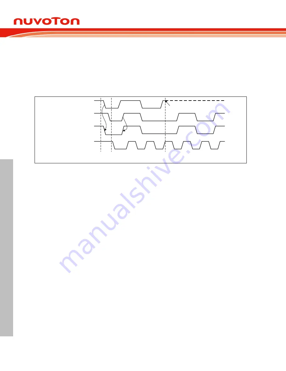
Arbitration is carried out by all masters continuously monitoring the SDA line after outputting data. If
the value read from the SDA line does not match the value that the master has to output, it has lost
the arbitration. Note that a master can only lose arbitration when it outputs a high SDA value while
another master outputs a low value. Arbitration will continue until only one master remains, and this
may take many bits. Its first stage is a comparison of address bits, and if both masters are trying to
address the same device, arbitration continues on to the comparison of data bits or acknowledge bit.
DATA 1 from master 1
START
condition
Master 1 loses arbitration for DATA 1
≠
SDA
It immediately switches to not addressed slave
and outputs high level
DATA 2 from master 2
SDA line
SCL line
Figure 6.12-8 Arbitration Procedure of Two Masters
Since control of the I
2
C bus is decided solely on the address or master code and data sent by
competing masters, there is no central master, nor any order of priority on the bus. Slaves are not
involved in the arbitration procedure.
Operation Modes
6.12.3.5
The on-chip I
2
C ports support three operation modes, Master, Slave, and General Call Mode.
In a given application, I
2
C port may operate as a master or as a slave. In Slave mode, the I
2
C port
hardware looks for its own slave address and the general call address. If one of these addresses is
detected, and if the slave is willing to receive or transmit data from/to master(by setting the AA bit),
acknowledge pulse will be transmitted out on the 9th clock, hence an interrupt is requested on both
master and slave devices if interrupt is enabled. When the microcontroller wishes to become the bus
master, hardware waits until the bus is free before entering Master mode so that a possible slave
action is not be interrupted. If bus arbitration is lost in Master mode, I
2
C port switches to Slave mode
immediately and can detect its own slave address in the same serial transfer.
To control the I
2
C bus transfer in each mode, user needs to set I2C_CTL0, I2C_DAT registers
according to current status code of I2C_STATUS0 register. In other words, for each I
2
C bus action,
user needs to check current status by I2C_STATUS0 register, and then set I2C_CTL0, I2C_DAT
registers to take bus action. Finally, check the response status by I2C_STATUS0.
The bits, STA, STO and AA in I2C_CTL0 register are used to control the next state of the I
2
C
hardware after SI flag of I2C_CTL0 [3] register is cleared. Upon completion of the new action, a new
status code will be updated in I2C_STATUS0 register and the SI flag of I2C_CTL0 register will be set.
But the SI flag will not be set when I
2
C STOP. If the I
2
C interrupt control bit INTEN (I2C_CTL0 [7]) is
set, appropriate action or software branch of the new status code can be performed in the Interrupt
service routine.
Figure 6.12-9 Control I2C Bus according to the Current I2C Status shows the current I
2
C status code
is 0x08, and then set I2C_DATA=SLA+W and (STA,STO,SI,AA) = (0,0,1,x) to send the address to I
2
C
bus. If a slave on the bus matches the address and response ACK, the I2C_STATUS0 will be updated
by status code 0x18.


