General Description 2-25
Power OFF
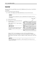
Follow the steps below to turn off the power. If NEC Express5800/ft series is plugged to a UPS, see
manuals included with the UPS or the application that controls the UPS.
1.
Perform a normal shutdown from Windows Server 2003.
The system will be powered off automatically. (Note: the POWER switch on the primary
side will remain illuminating when AC power is supplied.)
2.
Power off all peripheral devices.
POST Check
POST (power-on self test) is a self-test function stored on the motherboard of NEC Express5800/ft
series.
When you power on the server, POST will start automatically to check the motherboard, ECC
memory modules, CPU/IO modules, keyboard, mouse, etc. It also shows startup messages for
various BIOS setup utilities.
According to the factory default settings, the “NEC” logo appears on the display while POST is
being performed. (To view details of POST, press
Esc
.)
TIPS:
You can view POST details from the beginning without the need to press
Esc
when the
BIOS menu is displayed: select [System Configuration] - [Advanced], and set [Boot-time
Diagnostic Screen] to “Enabled” (see Chapter 4).
You can view the test items and details from a management PC where NEC ESMPRO
Manager is installed.
You do not always need to check POST details. You will need to check messages when:
You install a new NEC Express5800/ft series.
A failure is suspected.
You hear several beeps between the time of the power-on and OS start-up.
The display unit shows an error message.
Summary of Contents for Express5800/320Fd-MR
Page 13: ...v Appendix B I O Port Addresses This appendix lists factory assigned I O port addresses...
Page 19: ...xi THIS PAGE IS INTENTIONALLY LEFT BLANK...
Page 43: ...2 10 General Description Rear View...
Page 47: ...2 14 General Description CPU IO Module CPU IO module...
Page 67: ...2 34 General Description This page is intentionally left blank...
Page 79: ...3 12 Windows Setup and Operation 3 Confirm that RDR of the disk is cancelled...
Page 106: ...Windows Setup and Operation 3 39 This page is intentionally left blank...
Page 198: ...4 92 System Configuration This page is intentionally left blank...
Page 370: ......
Page 371: ...This page is intentionally left blank...
Page 389: ...6 18 Maintenance 3 Stop of PCI module 1 4 Start of PCI module 1...
Page 391: ...6 20 Maintenance This page is intentionally left blank...
Page 465: ...System Upgrade 8 31 board must not be mixed with N8804 005 or N8803 035...
Page 480: ......
Page 483: ......

