Installing and Using Utilities 5-141
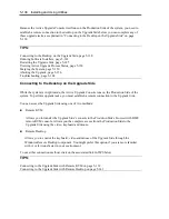
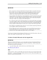
Connecting to the Upgrade Side with Remote Desktop
Remote Desktop allows you to control the keyboard, video and mouse of the Upgrade Side through
the Windows Remote Desktop component.
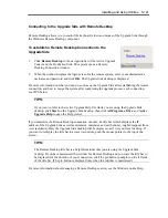
To establish a Remote Desktop Connection to the
Upgrade Side
1.
Click
Remote Desktop
in the navigation bar of the Active Upgrade
Console on the Production Side. The system opens a Remote
Desktop Connection window.
2.
When the window displays the login screen for the remote system, enter your administrative
username and password and click
OK
. The Upgrade Side desktop is displayed.
For more information on what you can do, such as on the Upgrade Side after establishing the remote
connection, and how to merge the system after completing the upgrade process, each connection,
see TIPS below
TIPS:
If you want to refer to the Active Upgrade Help file while you are using the Upgrade Side
desktop, click
Start
on the Upgrade Side desktop, then click
All Programs
,
ftSys
, and
Active
Upgrade Help
to open the Help viewer.
If you maximize the Remote Desktop connection window, its title bar (which displays the IP
address of the Upgrade Side as well as minimize, maximize and exit buttons), might disappear from
view (autohide). Only the Upgrade Side desktop will be displayed, as if it is your local desktop. If
you want to redisplay the title bar to access its controls, push the mouse pointer to the top of the
screen.
TIPS:
The Remote Desktop title bar is a helpful reminder that you are using the Upgrade Side
desktop. If you have maximized the window for Remote Desktop and you want the title bar to
be displayed for the duration of your connection, click the pin button (pushpin) on the left side
of the title bar. (The pin button is displayed only when the window is maximized.)
For more information about managing a Remote Desktop session, see the Windows online Help.
Summary of Contents for Express5800/320Fd-MR
Page 13: ...v Appendix B I O Port Addresses This appendix lists factory assigned I O port addresses...
Page 19: ...xi THIS PAGE IS INTENTIONALLY LEFT BLANK...
Page 43: ...2 10 General Description Rear View...
Page 47: ...2 14 General Description CPU IO Module CPU IO module...
Page 67: ...2 34 General Description This page is intentionally left blank...
Page 79: ...3 12 Windows Setup and Operation 3 Confirm that RDR of the disk is cancelled...
Page 106: ...Windows Setup and Operation 3 39 This page is intentionally left blank...
Page 198: ...4 92 System Configuration This page is intentionally left blank...
Page 370: ......
Page 371: ...This page is intentionally left blank...
Page 389: ...6 18 Maintenance 3 Stop of PCI module 1 4 Start of PCI module 1...
Page 391: ...6 20 Maintenance This page is intentionally left blank...
Page 465: ...System Upgrade 8 31 board must not be mixed with N8804 005 or N8803 035...
Page 480: ......
Page 483: ......

