System Upgrade 8-17
DIMM
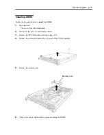
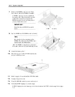
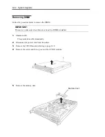
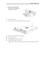
The DIMM (dual inline memory module) is installed to the DIMM socket in the CPU/IO module on
the NEC Express5800/ft series.
The CPU/IO module board is equipped with six sockets. A DIMM is installed on the CH0 slot 0 and
CH1 slot 0 as standard equipment. (The standard DIMMs can be replaced with other DIMMs.)
320Fd-LR/320Fd-MR model: 1GB DIMM×2
DIMMs should be installed in a set of 2 DIMMs, starting from the lowest socket number.
TIPS:
You can add memory up to 24 GB (4GB x 6).
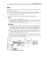
In the error messages and logs in POST NEC ESMPRO, or Off-line Maintenance Utility, the
DIMM connector may be described as “group.” The number next to “group” corresponds to
the slot number shown in the figure on the next page.
IMPORTANT:
The DIMM is extremely sensitive to static electricity. Make sure to touch the metal frame of
the server to discharge static electricity from your body before handling the DIMM. Do not
touch the DIMM terminals or onboard parts with a bare hand or place the DIMM directly on
the desk. For more information on static electricity, see “ANTI-STATIC MEASURES.”
Make sure to use the DIMM authorized by NEC. Installing a third-party DIMM may cause a
failure of the DIMM as well as the server. Repair of the server due to failures or damage
resulted from installing such a board will be charged.
Before adding or removing DIMMs, power off the server and detach the CPU/IO module.
Make sure to read “ANTI-STATIC MEASURES” and “PREPARING YOUR SYSTEM FOR
UPGRADE” before installing/removing DIMM.
Motherboard of the CPU/IO module
DIMM CH1 slot 2
DIMM CH1 slot 1
DIMM CH1 slot 0
DIMM CH0 slot 2
DIMM CH0 slot 1
DIMM CH0 slot 0
Summary of Contents for Express5800/320Fd-MR
Page 13: ...v Appendix B I O Port Addresses This appendix lists factory assigned I O port addresses...
Page 19: ...xi THIS PAGE IS INTENTIONALLY LEFT BLANK...
Page 43: ...2 10 General Description Rear View...
Page 47: ...2 14 General Description CPU IO Module CPU IO module...
Page 67: ...2 34 General Description This page is intentionally left blank...
Page 79: ...3 12 Windows Setup and Operation 3 Confirm that RDR of the disk is cancelled...
Page 106: ...Windows Setup and Operation 3 39 This page is intentionally left blank...
Page 198: ...4 92 System Configuration This page is intentionally left blank...
Page 370: ......
Page 371: ...This page is intentionally left blank...
Page 389: ...6 18 Maintenance 3 Stop of PCI module 1 4 Start of PCI module 1...
Page 391: ...6 20 Maintenance This page is intentionally left blank...
Page 465: ...System Upgrade 8 31 board must not be mixed with N8804 005 or N8803 035...
Page 480: ......
Page 483: ......

