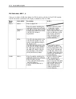
2-24 General Description
Power ON
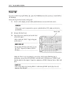
To power on NEC Express5800/ft series, press the POWER switch (the one whose in-built LED is
illuminating).
Follow the steps below to turn on the power.
1.
Power on the display unit and other peripheral devices connected to the server.
CHECK:
If the power cord is connected to a power controller like a UPS, make sure that it is
powered on.
2.
Remove the front bezel.
3.
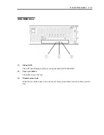
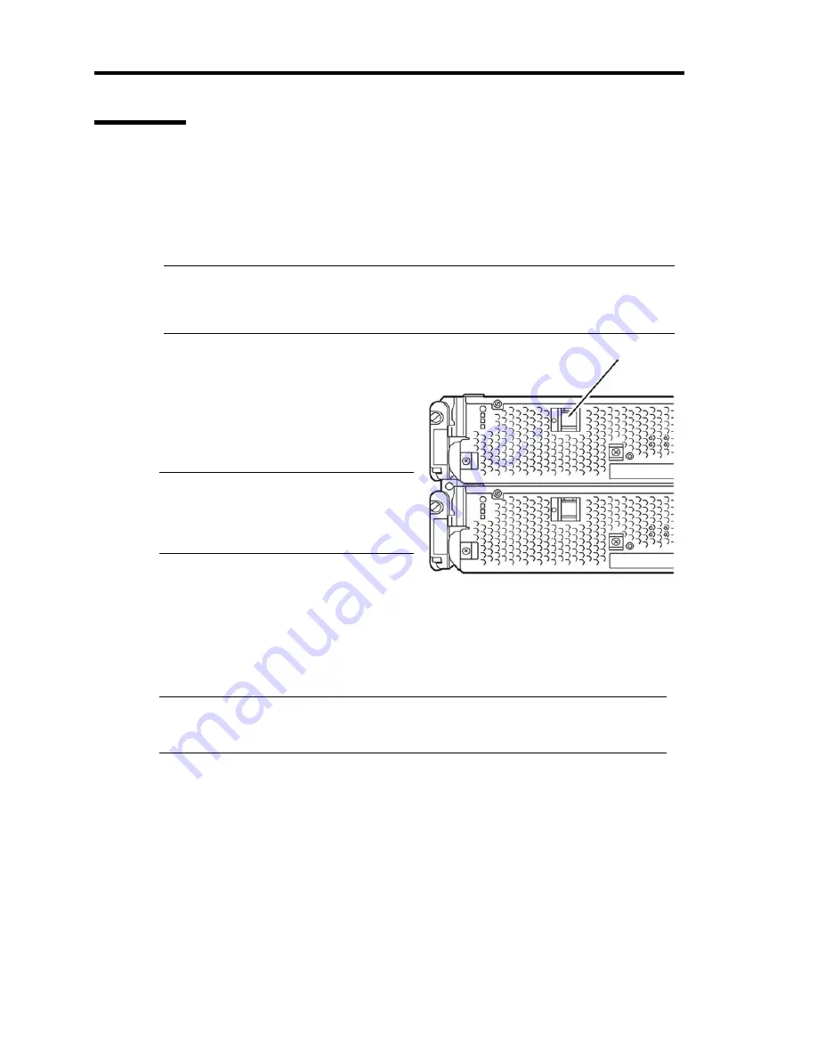
Press the power switch located on the front
of the front panel.
After a while, the “NEC” logo will appear
on the screen.
IMPORTANT:
Do not turn off the power before you see
the “NEC” logo and a character below
the logo.
While the “NEC” logo is displayed on the screen, NEC Express5800/ft series is
performing a power-on self test (POST) to check itself. For details, see “POST Check”
described later in this chapter. Upon the completion of POST, Windows Server 2003 will
start.
CHECK:
If the server finds errors during POST, it will interrupt POST and display the error
message. See Chapter 7.
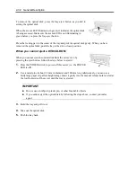
Power switch
Summary of Contents for Express5800/320Fd-MR
Page 13: ...v Appendix B I O Port Addresses This appendix lists factory assigned I O port addresses...
Page 19: ...xi THIS PAGE IS INTENTIONALLY LEFT BLANK...
Page 43: ...2 10 General Description Rear View...
Page 47: ...2 14 General Description CPU IO Module CPU IO module...
Page 67: ...2 34 General Description This page is intentionally left blank...
Page 79: ...3 12 Windows Setup and Operation 3 Confirm that RDR of the disk is cancelled...
Page 106: ...Windows Setup and Operation 3 39 This page is intentionally left blank...
Page 198: ...4 92 System Configuration This page is intentionally left blank...
Page 370: ......
Page 371: ...This page is intentionally left blank...
Page 389: ...6 18 Maintenance 3 Stop of PCI module 1 4 Start of PCI module 1...
Page 391: ...6 20 Maintenance This page is intentionally left blank...
Page 465: ...System Upgrade 8 31 board must not be mixed with N8804 005 or N8803 035...
Page 480: ......
Page 483: ......

