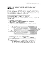
Windows Setup and Operation 3-35
4.
Restart the PCI module.
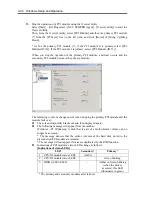
From the ft server utility, click [Up] of [Bring Up/Bring Down] to the PCI module
which was stopped in the step 3, and the PCI module will be started. Once the PCI
module is started, PCI module diagnosis, mirror volume duplication and PCI module
duplication are performed.
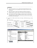
IMPORTANT:
If BrightStor ARCserve 2000 or Backup Exec is installed, the tape will not be
recognized due to the failover of the PCI module. Thus be sure to stop the services
before starting the PCI module.
1. Start [Services] from [Administrative Tools] of [Control Panel].
2. Select a service of backup software.
3. Choose “Stop” from the “Action” menu.
4. Repeat 2 and 3 for all services of the backup software.
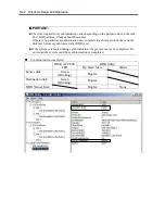
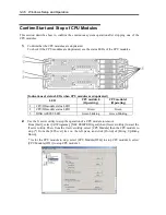
The PCI modules’ status LEDs changes as shown below:
[Indications of the status LEDs]
Immediately after the PCI module startup until the completion of diagnosis
LED Secondary
Primary
1
CPU/IO module status LED1
-
-
2
CPU/IO module status LED2
-
Green blinking
3
DISK ACCESS LED
-
Amber or Green blinking
(when the disk is accessed,
this LED illuminates in
green)
When duplication of disks is started after the completion of PCI module diagnosis
* The status of LEDs varies depending on the method of disk duplication.
LED Secondary
Primary
1 CPU/IO module status
LED1
-
-
2 CPU/IO module status
LED2
Green blinking
Green blinking
3
DISK ACCESS LED
Amber or Green
blinking (when the disk
is accessed, this LED
illuminates in green)
Amber or Green
blinking (when the disk
is accessed, this LED
illuminates in green)
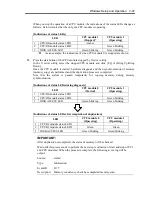
After the completion of disk duplication and when the PCI modules are duplicated
LED Secondary
Primary
1
CPU/IO module status LED1
-
-
2
CPU/IO module status LED2
Green
Green
3
DISK ACCESS LED
Green blinking
Green blinking
Summary of Contents for Express5800/320Fd-MR
Page 13: ...v Appendix B I O Port Addresses This appendix lists factory assigned I O port addresses...
Page 19: ...xi THIS PAGE IS INTENTIONALLY LEFT BLANK...
Page 43: ...2 10 General Description Rear View...
Page 47: ...2 14 General Description CPU IO Module CPU IO module...
Page 67: ...2 34 General Description This page is intentionally left blank...
Page 79: ...3 12 Windows Setup and Operation 3 Confirm that RDR of the disk is cancelled...
Page 106: ...Windows Setup and Operation 3 39 This page is intentionally left blank...
Page 198: ...4 92 System Configuration This page is intentionally left blank...
Page 370: ......
Page 371: ...This page is intentionally left blank...
Page 389: ...6 18 Maintenance 3 Stop of PCI module 1 4 Start of PCI module 1...
Page 391: ...6 20 Maintenance This page is intentionally left blank...
Page 465: ...System Upgrade 8 31 board must not be mixed with N8804 005 or N8803 035...
Page 480: ......
Page 483: ......

