8-28 System Upgrade
IMPORTANT:
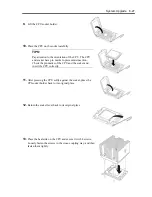
Place the heat sink so that its corners will not bump
against the parts on the motherboard.
14.
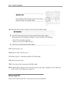
Check that the heat sink is attached to the mother board horizontally.
IMPORTANT:
If the heat sink is tilted, remove the heat sink and then attach it again.
If the heat sink is not attached horizontally, it may be caused by the following.
- The CPU is not attached correctly.
- Screws are not secured tightly enough.
Do not move around the heat sink fastened.
15.
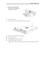
Connect the duct cover.
16.
Fasten the cable to the duct cover.
17.
Refer to page 8-15 and attach install the CPU/IO module.
18.
Connect the power cord.
19.
Turn on the power by pressing the POWER switch.
20.
Verify that POST displays no error message. If an error message is displayed, write it down and
check it in the error message list on page 7-4.
Removing CPU
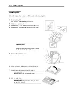
Removal of a heat sink and CPU is the reverse procedure of installation.
Summary of Contents for Express5800/320Fd-MR
Page 13: ...v Appendix B I O Port Addresses This appendix lists factory assigned I O port addresses...
Page 19: ...xi THIS PAGE IS INTENTIONALLY LEFT BLANK...
Page 43: ...2 10 General Description Rear View...
Page 47: ...2 14 General Description CPU IO Module CPU IO module...
Page 67: ...2 34 General Description This page is intentionally left blank...
Page 79: ...3 12 Windows Setup and Operation 3 Confirm that RDR of the disk is cancelled...
Page 106: ...Windows Setup and Operation 3 39 This page is intentionally left blank...
Page 198: ...4 92 System Configuration This page is intentionally left blank...
Page 370: ......
Page 371: ...This page is intentionally left blank...
Page 389: ...6 18 Maintenance 3 Stop of PCI module 1 4 Start of PCI module 1...
Page 391: ...6 20 Maintenance This page is intentionally left blank...
Page 465: ...System Upgrade 8 31 board must not be mixed with N8804 005 or N8803 035...
Page 480: ......
Page 483: ......

