Installing and Using Utilities 5-71
7.
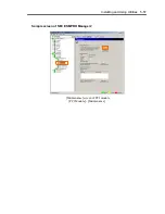
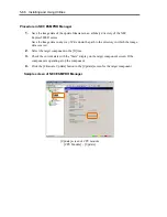
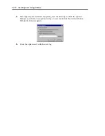
After the BIOS for a single CPU module is completed, click the [Jump Switch] button.
The module completely updated is started and the module under operation is stopped.
8.
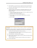
Start the other inactive module.
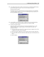
Starting the module causes the firmware to be updated automatically. However, if the
[Enable automatic firmware update] property is disabled, update the module in the
procedure as follows:
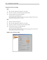
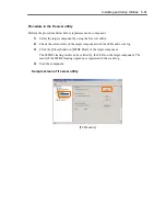
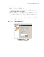
(1) Check the current state with the “State” display on the target component screen. If the
component is operating, stop the component.
(2) Click the [Firmware...] button for the target component.
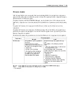
(3) Select the update method in the [Firmware Update] dialog box and click the
[Activate] button.
(4) Start the module.
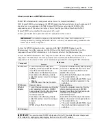
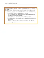
Even if you do not have the image data of firmware for update, the firmware can be copied from the
other module.
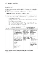
By starting the module, the firmware will be updated automatically. However, when the [Enable
automatic firmware update] property is disabled, follow the steps below to update the firmware:
1.
Start the system using the module of the firmware copy source.
See the current status by the “Status” indication on the target component screen of the
copy destination and verify that it is stopped.
2.
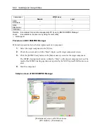
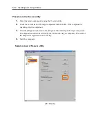
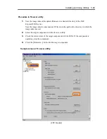
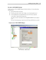
Click the [Firmware...] button for the target component.
3.
When a firmware updating dialog appears, check [Copy firmware from Online module to
Offline one] and execute it.
Firmware is updated by copying the firmware on the online side to the offline side.
4.
Start the stopped module.
Summary of Contents for Express5800/320Fd-MR
Page 13: ...v Appendix B I O Port Addresses This appendix lists factory assigned I O port addresses...
Page 19: ...xi THIS PAGE IS INTENTIONALLY LEFT BLANK...
Page 43: ...2 10 General Description Rear View...
Page 47: ...2 14 General Description CPU IO Module CPU IO module...
Page 67: ...2 34 General Description This page is intentionally left blank...
Page 79: ...3 12 Windows Setup and Operation 3 Confirm that RDR of the disk is cancelled...
Page 106: ...Windows Setup and Operation 3 39 This page is intentionally left blank...
Page 198: ...4 92 System Configuration This page is intentionally left blank...
Page 370: ......
Page 371: ...This page is intentionally left blank...
Page 389: ...6 18 Maintenance 3 Stop of PCI module 1 4 Start of PCI module 1...
Page 391: ...6 20 Maintenance This page is intentionally left blank...
Page 465: ...System Upgrade 8 31 board must not be mixed with N8804 005 or N8803 035...
Page 480: ......
Page 483: ......

