Installing and Using Utilities 5-145
Restarting the Upgrade Side
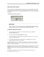
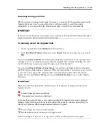
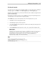
When the system is running in split mode, if necessary, you can restart the operating system on the
Upgrade Side at any time. You can either allow a software installer to restart the system
automatically or you can perform the following procedure to restart the system manually.
IMPORTANT:
Before you restart the system, ensure that you are working on the Upgrade Side desktop (through a
remote connection). Do not restart the Production Side.
To manually restart the Upgrade Side
1.
On the Upgrade Side, click
Shut Down
in the Start menu.
2.
In the
Shut Down Windows
dialog box, select
Restart
from the drop-down menu and click
OK
.
If you are using
Remote KVM
, the AVR session will remain connected while the Upgrade Side is
restarting; however, you must log on again when the Upgrade Side is finished restarting. (To send
the Ctrl-Alt-Del key sequence necessary for login, use a virtual keyboard.)
If you are using
Remote Desktop Connection
, the connection to the Upgrade Side is terminated,
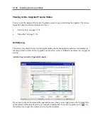
and the Production Side desktop is displayed. While the Upgrade Side is restarting, you can view its
status in the activity log and the status bar of the Active Upgrade Console. When the console
displays the message
Partner: OS Up
, you can click
Remote Desktop
to log on to the Upgrade
Side again.
IMPORTANT:
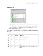
When you restart the Upgrade Side, the following activity log may be displayed on the Active
Upgrade Console:
Partner (Upgrade) state is now Hung:
Unexpected state transition in Split state.
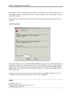
There may be an output of these activity logs even when the Upgrade Side’s restart completed
normally. If the following activity logs are displayed after about five minutes, select [Retry] to
retry the split process so that you can continue the Active Upgrade.
Partner (Upgrade) state is now Running OS.
Reestablished network connection with Upgrade side.
If there is no output of those acvtivity logs, select [Abort] to interrupt the Active Upgrade.
Summary of Contents for Express5800/320Fd-MR
Page 13: ...v Appendix B I O Port Addresses This appendix lists factory assigned I O port addresses...
Page 19: ...xi THIS PAGE IS INTENTIONALLY LEFT BLANK...
Page 43: ...2 10 General Description Rear View...
Page 47: ...2 14 General Description CPU IO Module CPU IO module...
Page 67: ...2 34 General Description This page is intentionally left blank...
Page 79: ...3 12 Windows Setup and Operation 3 Confirm that RDR of the disk is cancelled...
Page 106: ...Windows Setup and Operation 3 39 This page is intentionally left blank...
Page 198: ...4 92 System Configuration This page is intentionally left blank...
Page 370: ......
Page 371: ...This page is intentionally left blank...
Page 389: ...6 18 Maintenance 3 Stop of PCI module 1 4 Start of PCI module 1...
Page 391: ...6 20 Maintenance This page is intentionally left blank...
Page 465: ...System Upgrade 8 31 board must not be mixed with N8804 005 or N8803 035...
Page 480: ......
Page 483: ......


