System Upgrade 8-43
4.
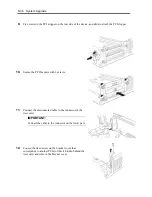
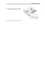
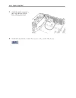
Fix the card and the bracket with a screw.
5.
Remove the blank cover by removing the screw.
6.
Put a LAN cable through a hole from
outside the server and plug the LAN
connector (the bigger connector) to
the back of the chassis.
Make sure you see two hooks on the
both sides of the LAN connector and
hear the snap sound as you fix the
LAN connector.
LAN connector
Hook
LAN
cable
Blank cover
Summary of Contents for Express5800/320Fd-MR
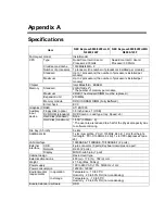
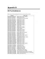
Page 13: ...v Appendix B I O Port Addresses This appendix lists factory assigned I O port addresses...
Page 19: ...xi THIS PAGE IS INTENTIONALLY LEFT BLANK...
Page 43: ...2 10 General Description Rear View...
Page 47: ...2 14 General Description CPU IO Module CPU IO module...
Page 67: ...2 34 General Description This page is intentionally left blank...
Page 79: ...3 12 Windows Setup and Operation 3 Confirm that RDR of the disk is cancelled...
Page 106: ...Windows Setup and Operation 3 39 This page is intentionally left blank...
Page 198: ...4 92 System Configuration This page is intentionally left blank...
Page 370: ......
Page 371: ...This page is intentionally left blank...
Page 389: ...6 18 Maintenance 3 Stop of PCI module 1 4 Start of PCI module 1...
Page 391: ...6 20 Maintenance This page is intentionally left blank...
Page 465: ...System Upgrade 8 31 board must not be mixed with N8804 005 or N8803 035...
Page 480: ......
Page 483: ......

