Troubleshooting 7-19
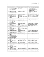
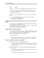
Exclamation mark “!” appears to “VGA Display Controller” under the “non-Plug and
Play device” when changed the setting to show hidden devices in menu in the
Device Manager:
This has to do with the server specification and there is no effect to the operation.
Exclamation mark “!” appears to “VGA Display Controller” since OS Standard VGA
driver is not activated in the server.
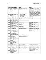
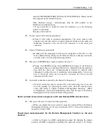
Warning message appears in POST after implementing ft Remote Management Card:
Did you set “Initialize Remote Management Card”?
H/W Configuration of BMC is corrupted.
!! Update BMC H/W Configuration by configuration tool!!
!! Refer to BMC Configuration manual !!
If the message above appears, press
F1
key or wait for a while. Then POST
proceeds. Insert NEC EXPRESSBUILDER DVD attached to the server to the
DVD-ROM drive to start NEC EXPRESSBUILDER. Select [Tools] - [Initialize
Remote Management Card] from its main menu to write the sensor information
specific to the server to the card.
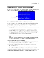
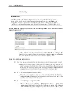
A CPU/IO module cannot be integrated:
When a componet fails and is reintegrated, the following message may be recorded
to the system event log and the process is stopped. Such event indicates that the
component’s MTBF is below the threshold and it is judged that repair is necessary.
Thus the reintegration process cannot be completed. Generally replacement of the
component will be required, so contact your sales representative. If reintegraating the
component without repair is required for some reason, consult your sales agent. It is
possible to perform reintegration forcefully.
Source:
srabid
ID:
16395
Description: x is now STATE BROKEN / REASON_BELLOW_MTBF (“x” is a
device number.)
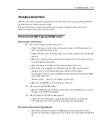
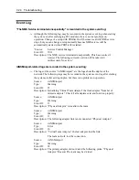
When you integrate a PCI module when exchanging, starting and diagnosing the PCI
module, follwing events may be recorded on [System] in [Event Viewer], and the
duplex process may fail:
Source:
srabid
ID:
16474
Description: Diagnostics failure of XX: ‘IO GbEnet OUI Verification 1, D821’
(Ftn=xxxx Info=xxxx,xxxx).
Summary of Contents for Express5800/320Fd-MR
Page 13: ...v Appendix B I O Port Addresses This appendix lists factory assigned I O port addresses...
Page 19: ...xi THIS PAGE IS INTENTIONALLY LEFT BLANK...
Page 43: ...2 10 General Description Rear View...
Page 47: ...2 14 General Description CPU IO Module CPU IO module...
Page 67: ...2 34 General Description This page is intentionally left blank...
Page 79: ...3 12 Windows Setup and Operation 3 Confirm that RDR of the disk is cancelled...
Page 106: ...Windows Setup and Operation 3 39 This page is intentionally left blank...
Page 198: ...4 92 System Configuration This page is intentionally left blank...
Page 370: ......
Page 371: ...This page is intentionally left blank...
Page 389: ...6 18 Maintenance 3 Stop of PCI module 1 4 Start of PCI module 1...
Page 391: ...6 20 Maintenance This page is intentionally left blank...
Page 465: ...System Upgrade 8 31 board must not be mixed with N8804 005 or N8803 035...
Page 480: ......
Page 483: ......

