Command
System state
①
Starting lockout
ISDSH Safe Standstill (STO)
②
Ready for start
ENPO EnablePower
③
On
Bit (0) = START(1)
④
Active control
Active control
Legend for Time diagram of sequences
9.2.8 Pulse direction
Pulse direction can be realized using the MSD PLC or EGEAR (electrical gearing).
With EGEAR, control is carried out in the control mode “Term (1) via terminals” as
follows.
Setting the control mode
Setting of the manner in which the control is to be carried out.
Invoke Motion profile -> Basic setting.
Set “Term (1) = set via terminals” under “Control via.” The setting for the reference
under “Reference via” is irrelevant.
Parameter setting for speed/direction
Set parameter P 1400 (MPRO_TP_config) to “PC_PC(4)” (= TP0, pulse counter, TP1,
pulse counter ). The speed, but not the direction, can be changed.
Setting P 1400 (MPRO_TP_config) to “PD_UP(2)” (TP0, TP1 as encoder; pulse (TP0)
/ direction (TP1), count up on direction high) means both the speed and the direction
can be changed. To find out which setting is possible, see the description of the
parameter. Parameter P 1404 (MPRO_TP_Lines) is used to set the resolution
(pulses/revolution).
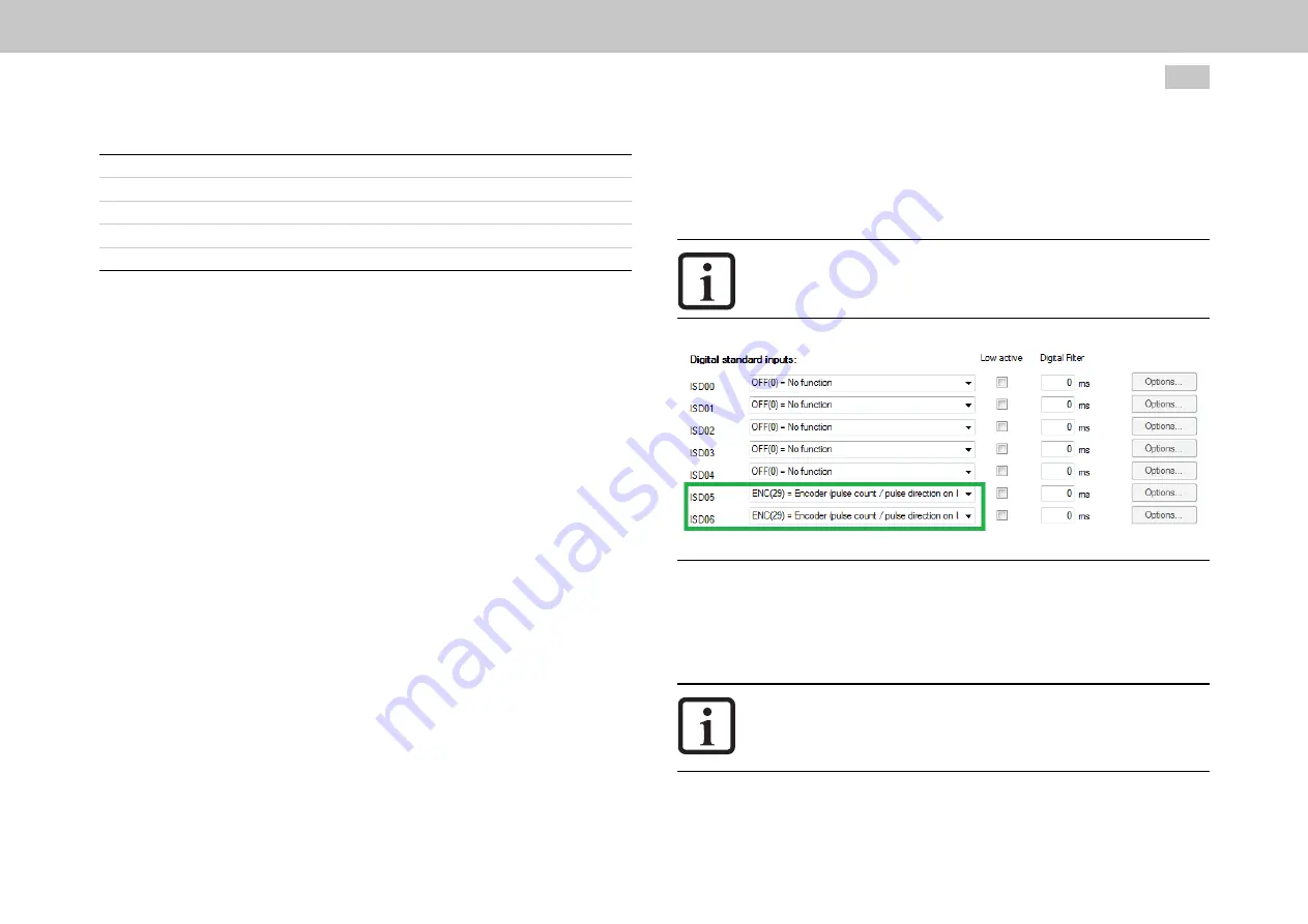
Setting the digital standard inputs ISD05 and ISD06
MOOG
ID No.: CB40859-001 Date: 11/2020
MSD Servo Drive - Device Help
296
9 Inputs/Outputs settings
The setting can be made in the dialog box I/O configuration -> Dig. inputs.
Set ISD05 and ISD06 to ENC(29) = Encoder (pulse count / pulse direction on ISD05,
ISD06 only).
NOTE
l
The electrical connection is made via terminals X4/20 (ISD05) and
X4/21 (ISD06 ).
Image 9.5: Digital inputs pulse direction
Setting the electrical gearing (EGEAR)
Invoke Motion profile -> Synchronized motion.
Set the electrical gearing (EGEAR) according to the following figures.
NOTE
l
If
P 1404
(MPRO_TP_Lines) is not set [factory setting is 1 pulse =
1 revolution], then the gear ratio is important for the speed of the
rotor.


