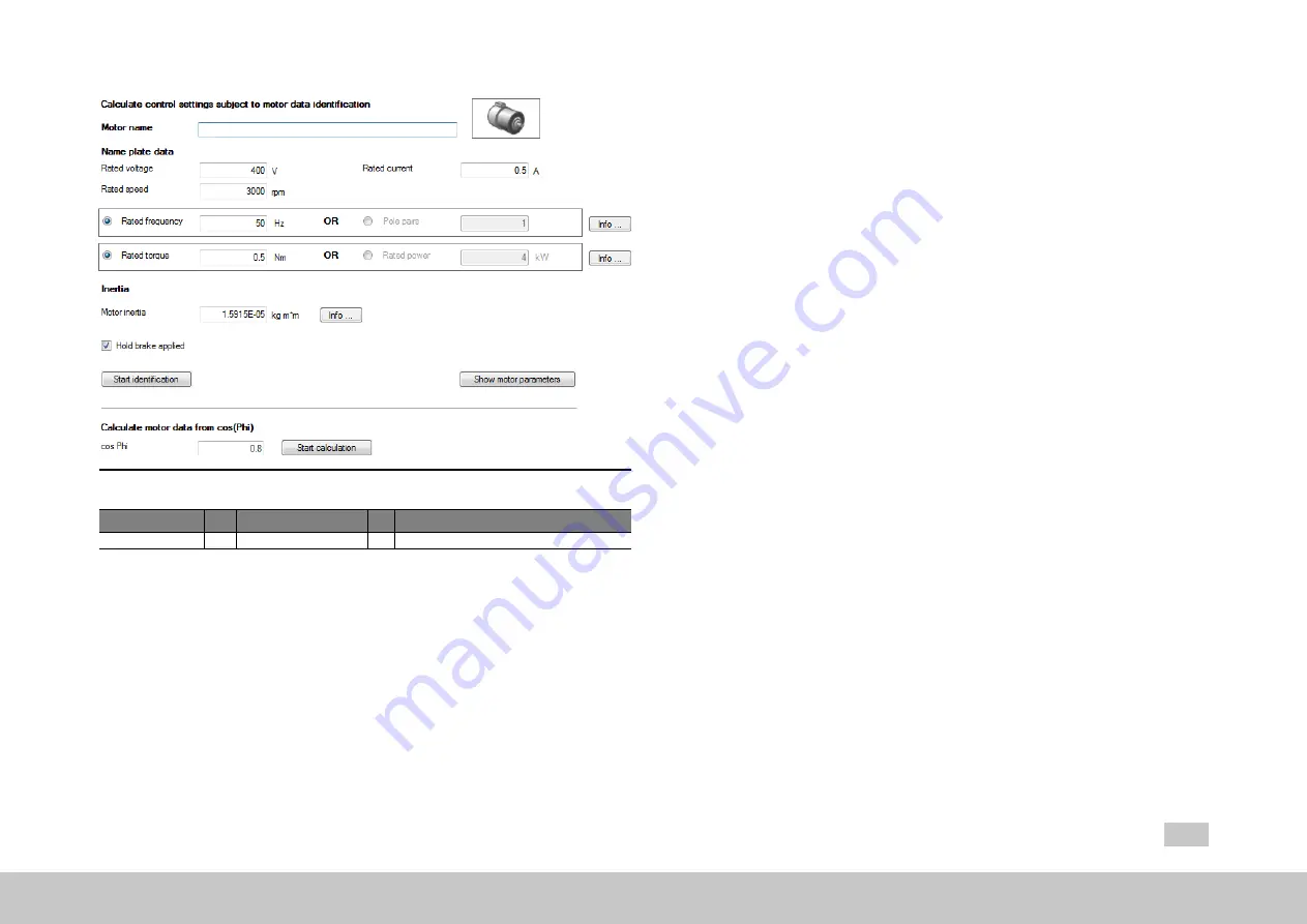
Image 5.13: “Motor identification" screen for an asynchronous motor
ID
Index Name
Unit Description
1531
0
SCD_Action_Sel
Self-commissioning action selection
Table 5.9: “Motor identification” parameters
When the Rating plate data have been entered in the screen, identification is started
by clicking the "Start identification" button. A safety notice must be confirmed with a
tick (check mark).
MOOG
ID No.: CB40859-001 Date: 11/2020
MSD Servo Drive - Device Help
46
5 Motor
5.6.1 Synchronous motor identification (rotary and linear)
l
Enter the motor data.
l
Click "Identification" button
l
Current controller tuning: optimization of the current controller is done
automatically.
5.6.2 Asynchronous motor identification
l
Current controller tuning
l
Measurement of:
P 470[0] - MOT_Rstat
: Stator resistance,
P 476[0] - MOT_
Rrot
: Rotor resistance,
P 471[0] - MOT_Lsig
: Leakage inductance
l
Maximum effective current Idmax
P 474[0] - MOT_LmagIdNom
l
Operating point calculation:
P 462[0] - MOT_FluxNom
: Nominal flux,
P 340
[0] - CON_FM_Imag
: Magnetizing current
l
Calculation of: current, speed and position control parameters
l
Click the "Start calculation" button to determine the rotor resistance
P 476[0] -
MOT_Rrot
and leakage inductance
P 471[0] - MOT_Lsig
.
l
Measurement of the saturation characteristic (table values of the stator
inductance
P 472 - MOT_LSigDiff
);
Measurements are taken up to four times rated current, provided the power
stage current permits it at standstill. If this is not the case, the measurement is
made using a correspondingly smaller current.
l
P 340[0] - CON_FM_Imag
Magnetizing current


