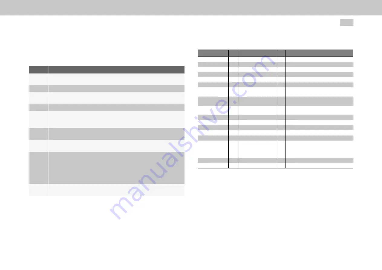
6.8.2.1 Activation of sensorless control for asynchronous motors
Proceed as follows:
No.
Activity
1
Set motor type
(P 450[0] - MOT_Type
) to “2 (ASM) = asynchronous
motor”.
2
Enter the motor name
(P 451[0] - MOT_Name)
.
3
Copy the motor variables from the rating plate into the appropriate input
box.
4
Start motor identification to identify other motor parameters.
5
In the “Encoder selection” screen (
see also section "Encoder selection"
) under “Encoder for commutation and torque control,” set
P 520[0] - ENC_MCon
to “CH4(4) = virtual encoder (Channel 4)”.
6
Under “virtual encoder (Channel 4)” "Encoder selection" set
(P 508[0] -
ENC_CH4_Sel)
to "SFC(8) = take values of SFC model".
7
In the “Basic Control Settings” screen (see section “Basic settings” on
page 101) set “Speed filter TF” (
P 351[0] - CON_SCALC_Tf
) to 10 ms.
8
In the “Asynchronous motor control settings identification” screen (
also section "Asynchronous motor" on page 38
) enter the “Total moment
of inertia” of the system
(P 1516[0] - SCD_JSum
). Enter a value that is
too small rather than too big to avoid a tendency to oscillate. Automatic
detection is not advisable due to the control dynamics and accuracy
required.
9
In the same screen under “Control design by stiffness” set
P 1515[0] -
SCD_ConDesign (Stiffness)
to 10%.
Table 6.31: Commissioning a sensorless-controlled asynchronous motor
MOOG
ID No.: CB40859-001 Date: 11/2020
MSD Servo Drive - Device Help
98
6 Encoder
Additional setting parameters
P No.
Index Name
Unit Description
351
CON_SCALC_Tf
Speed filter
0
CON_SCALC_Tf
ms
Filter time const. speed control (motor)
1
CON_SCALC_Tf
ms
Filter time const. velocity (hydraulic cyl.)
2
CON_SCALC_Tf
ms
Filter time const. speed from position control.
792
EN_CH4_Kalman_SigInj
Sensorless control: Test signal generator.
0
Signal
7
FullSignalRange
rpm SC test signal: Linear transition range up until
which the test signal is reduced to 0.
8
IncreasingSignalRange
rpm SC test signal: Linear transition range up until
which the test signal is reduced to 0.
9
d current offset
A
SC test signal: d current offset of sinusoidal
signal.
1959
CON_SFC_Para
SFC Parameter
0
TF_is
ms
filter time constant of isd/isq.
1
K_ov
%
Anti-overturning limitation factor.
2
K_isd
%
d-axis current control scaling.
3
Tstart
ms
start-up time (flux settling).
1973
CON_SFC_VoltageError
Settings for SFC voltage errors model. Low
voltage characteristic: must be set during the
motor identification; may require some
coordination effort.
0
I_err
A
low-voltage characteristic: corner current
1
V_err
V
low-voltage characteristic: corner voltage.
Table 6.32: "Sensorless control of asynchronous motor” parameter


